
This page shows instructions for version 2.1 of the robotic xylophone which uses an SD Card for the data storage. Instructions for version 2.0, using SPI Flash, are here.
Cutting and drilling the wood pieces to size requires some basic wood-shop tools, such as a cross-cut saw, hand-drill or drill press, and router or jig saw. The four sides of the enclosure are contructed from 5-1/2″ x 1/4″ oak project boards. Start with cutting 2 of these boards to length of 22-3/4″ and 2 boards to length of 23-1/4″.
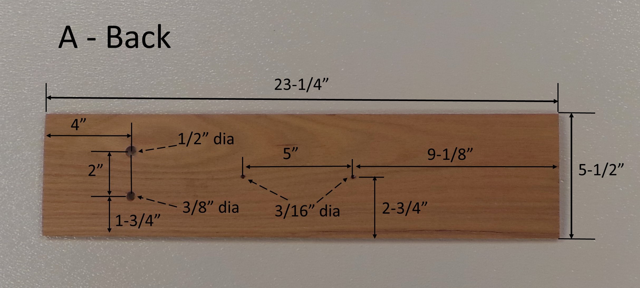
Piece “A”, the Back of the enclosure (when the xylophone is resting horizontally on a table), is 23-1/4″ long. Holes are drilled as shown below:
- 1/2″ diameter for the On/Off Toggle Switch
- 3/8″ diameter for the DC Barrel Jack
- Two 3/16″ diameter holes, 5″ apart, for the Handle
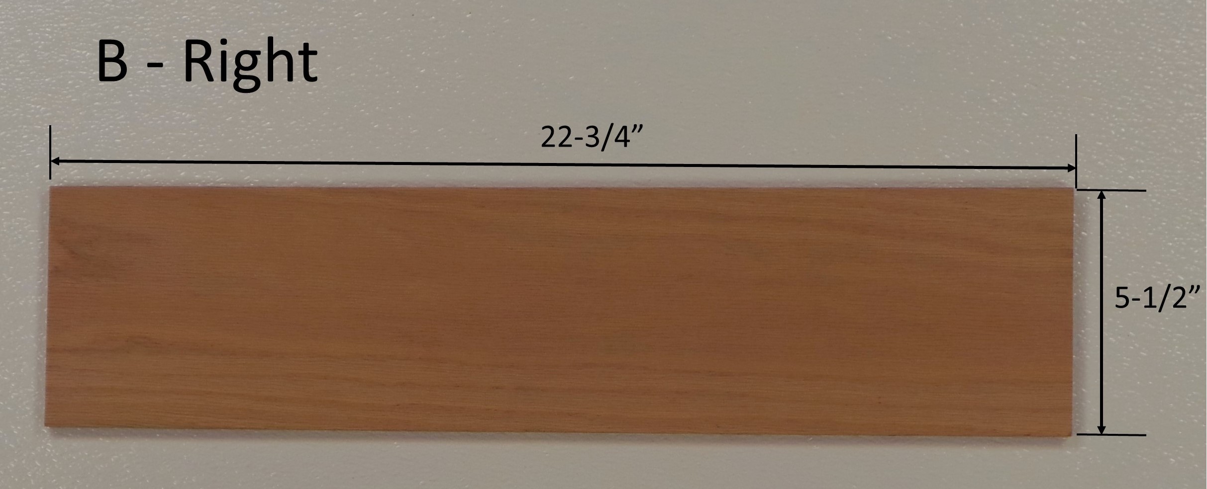
Piece “B”, the Right side of the enclosure, is 22-3/4″ long, and has no holes drilled.
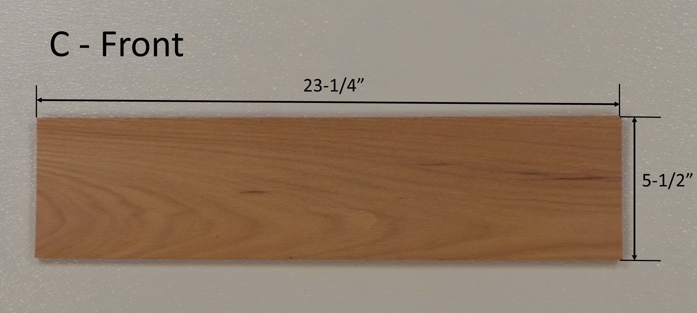
Piece “C”, the Front of the enclosure, is 23-1/4″ long and has no holes drilled.
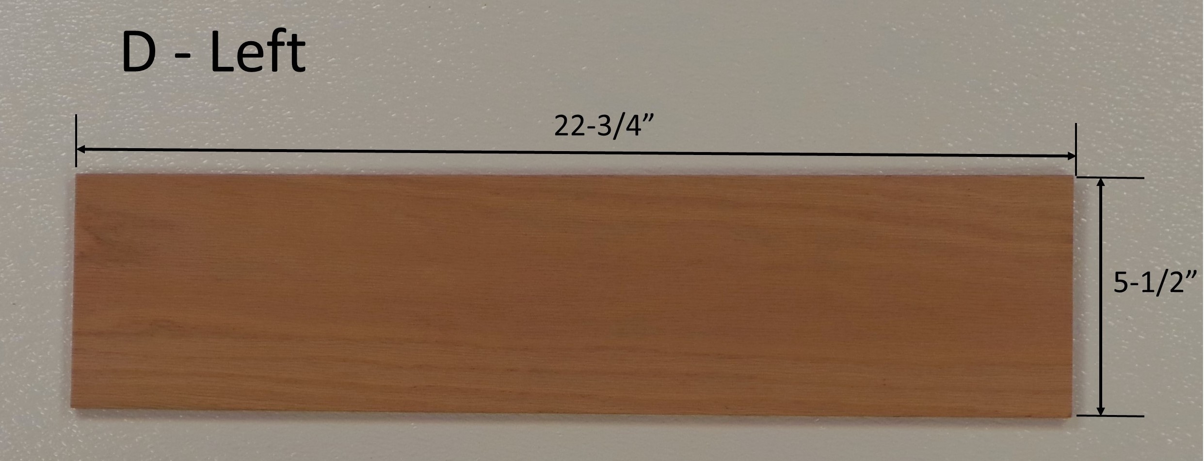
Piece “D”, the Left side of the enclosure, is 22-3/4″ long and had no holes drilled.
The Top and Bottom of the enclosure are cut from 1/4″ thick oak venier plywood. Start with a 2 ft x 4 ft plywood sheet and cut it into two squares, each one 22-3/4″ x 22-3/4″. Actually, I recommend cutting the sides of the Top and Bottom about 1/16″ to 1/8″ shorter than 22-3/4″, just so that it will fit without forcing.
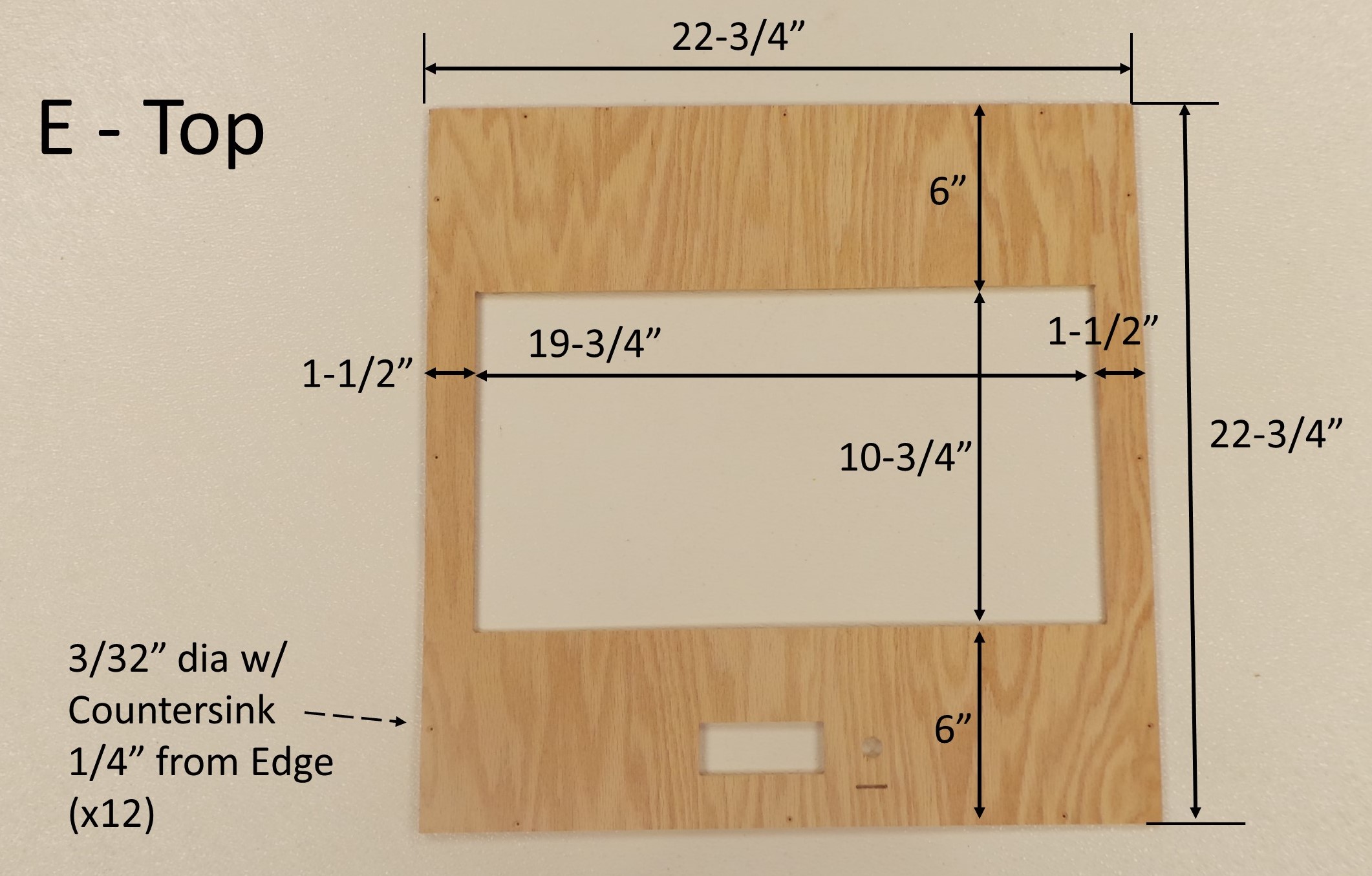
Piece “E” – the Top, needs to have the following holes dilled:
- 19-3/4″ x 10-3/4″ for the window
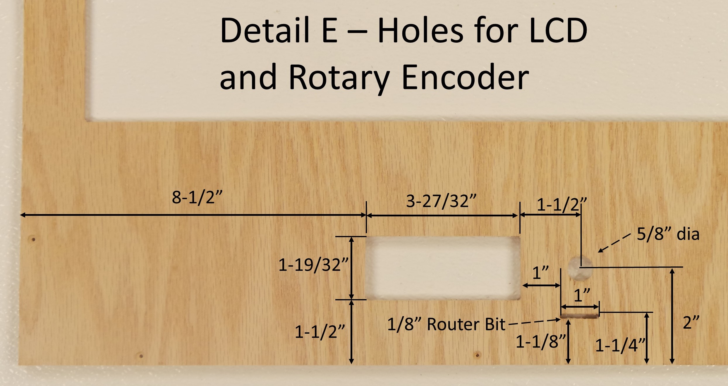
- 1-19/32″ x 3-27/32″ for 20×4 Character LCD
- 5/8″ diameter hole for Rotary Encoder
- 1/8″ x 1″ for the SD Card
- 3/32″ diameter holes, with countersink, 1/4″ from edge. Drill 3 of these holes on each side (total of 12). These will be used to secure the Top to the rest of the enclosure.
The rectangular holes for the window, LCD, and SD Card are cut using a 1/8″ straight router bit. See the Jigs page for more information.
Piece “F” – the Bottom is the same size as the top, and has the same 3/32″ holes along the four sides.
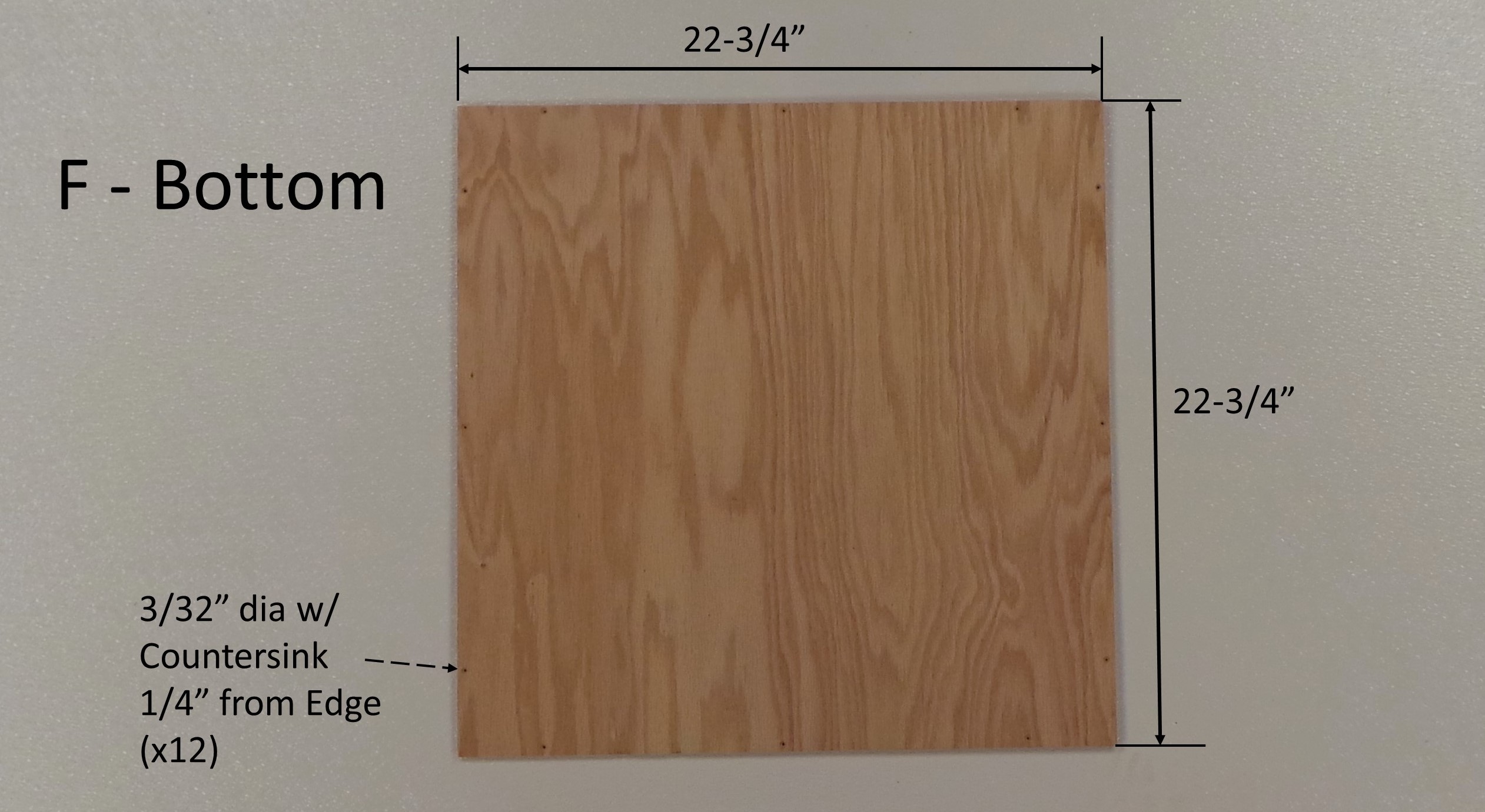
Note that using a countersink with the holes on the edge will allow a flat-head screw to be flush with the surface.
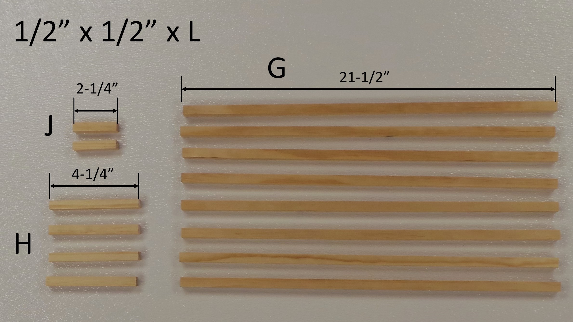
Pieces “G”, “H”, and “J” are cut from 1/2″ square dowels. Cut 8 of the “G” piece, each 21-1/2″ long, cut 4 of the “H” piece, each 4-1/4″ long, and cut 2 of the “J” piece, each 2-1/4″ long.
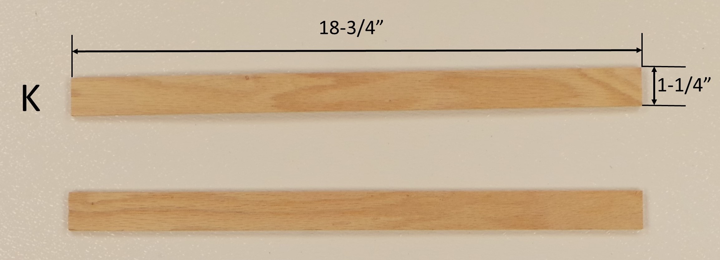
Pieces “K”, the two Runners are cut from the 1-1/4″ strip of plywood that is left over from cutting pieces “E” and “F”, the Top and Bottom of the enclosure. They pieces don’t have to be exactly 1-1/4″ wide. Anything between 1″ and 1-1/2″ will work. Cut 2 of the “K” piece, each one 18-3/4″ long.
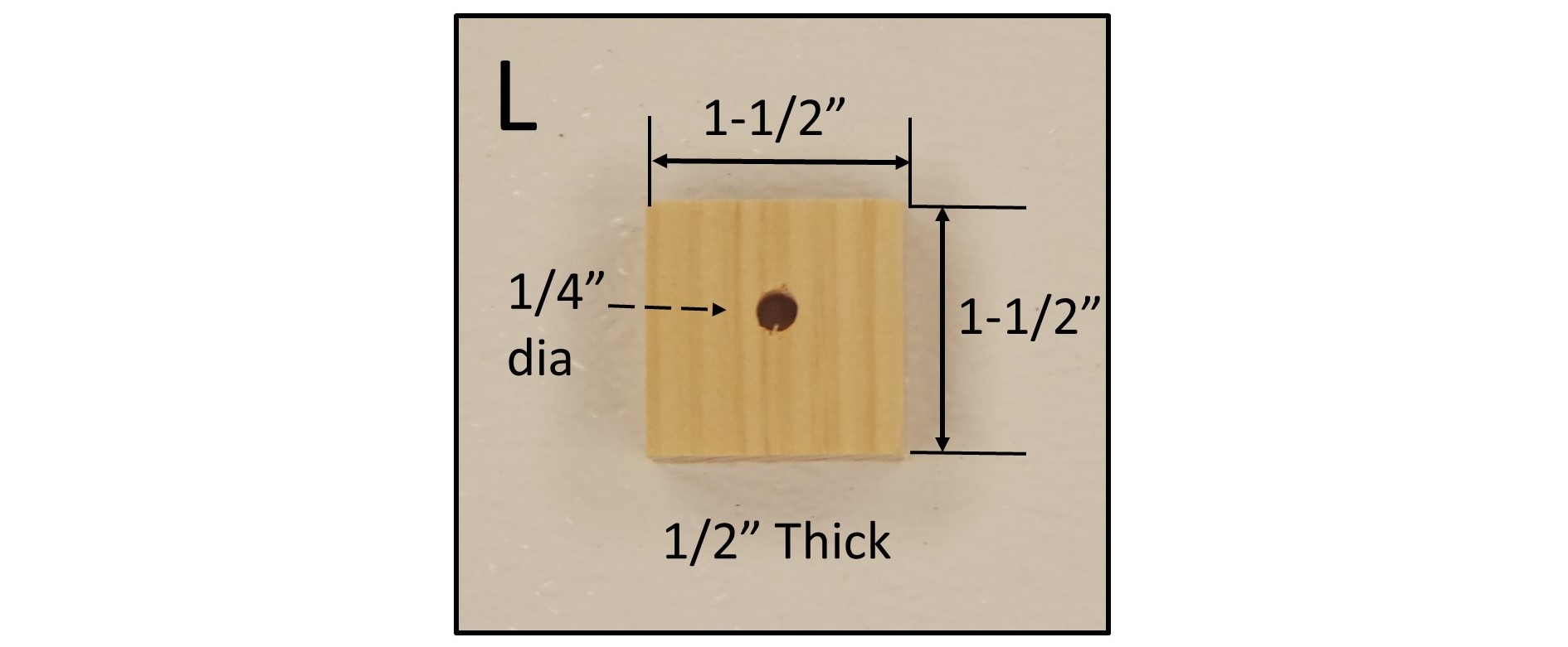
Piece “L” is the mount for the Rotary Encoder. It is a 1-1/2″ square piece cut from the 1/2″ x 1-1/2″ project board. Drill a 1/4″ diameter hole in the center of this piece. The KY-040 Rotary Encoder is secured by screwing it into the hole.
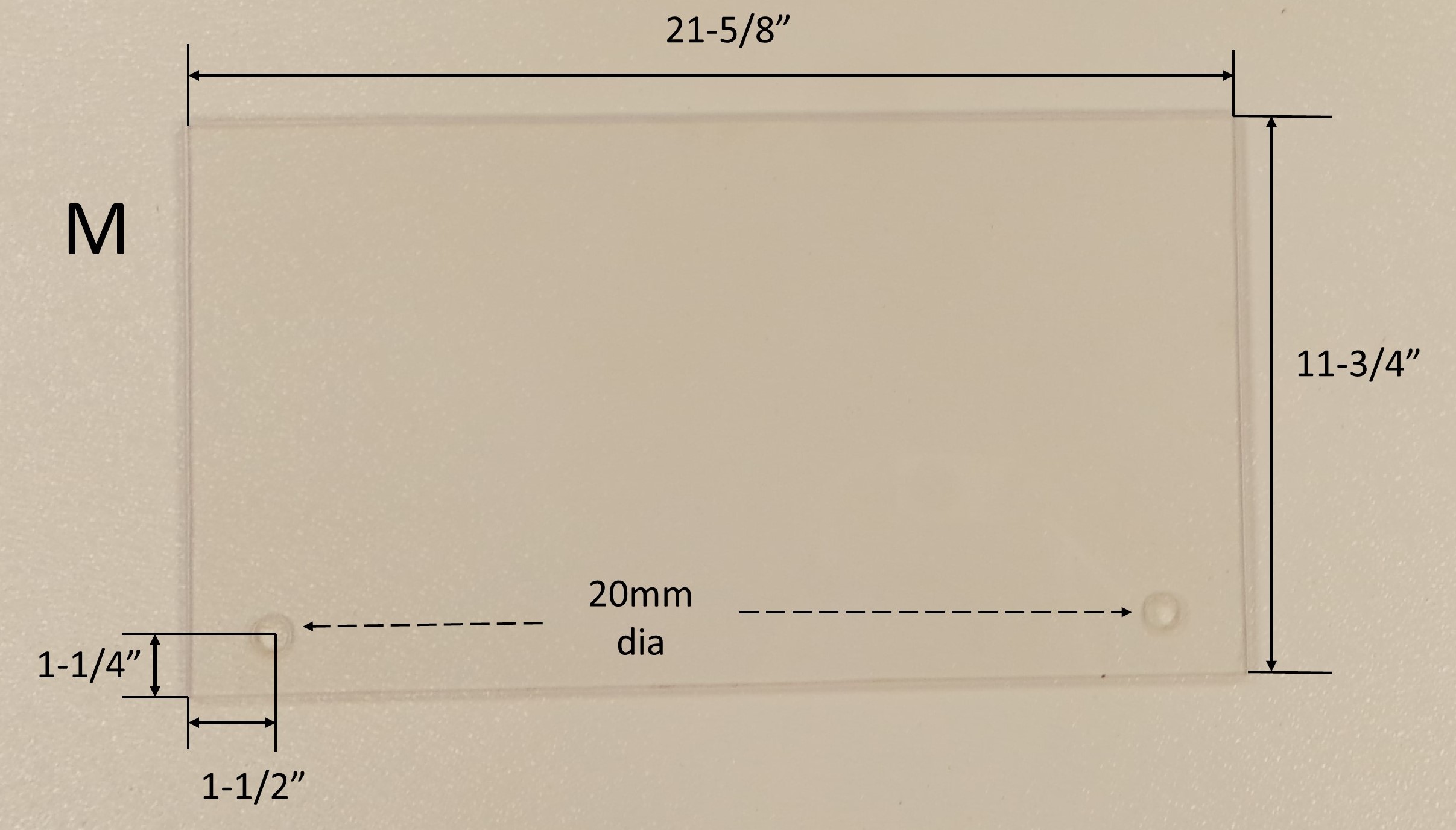
Piece “M”, the Window of the enclosure is made from a clear acrylic sheet, approximately 1/4″ thick. In this example, I used a the OPTIX 0.22-in x 18-in x 24-in Clear Acrylic Sheet from Lowes. This needs to be cut to a size 21-5/8″ x 11-3/4″. Drill a 20 mm hole near two of the corners as shown below. The holes are for the 3/4″ Closet Door Finger Pulls. I learned the hard way that the hole needs to be 20mm, not 3/4″. 20mm is just slightly larger than 3/4″. The Finger Pulls will not fit in the 3/4″ hole, and if you try to hammer it in, the acrylic sheet will crack.
Next: Gluing
