
The solenoids require 1A current at 12 VDC. This is significantly more voltage and current than can be driven directly from the Arduino board. (The Arduino I/O pins can drive only 40 mA at 5V).

If you Google “controlling solenoid with Arduino” you will find find a lot of different ways that this can be done. The simplest way (and what is shown in a lot of tutorials) is to use a TIP120 transistor, or something similar. This works just fine if you have just one or two solenoids. But for the robotic xylophone application, the wiring becomes somewhat cumbersome when you have 25 or more solenoids. In fact, when I built my original robotic xylophone, as you see described in the backgound, and shown on this video, I did it all with TIP120 transistors because at the time I didn’t know any other way.
One other option would be to use the ULN2803 8-channel Darlington Driver chip. This chip is basically 8 TIP120 transistors in one package. But this one also would require a lot of wiring and/or soldiering to make it work. Also, there would not be enough I/O pins on the Arduino Uno, so it would either need an Arduino Mega, or it would have to be used in conjunction with an I/O port expander, such as the MCP23008.
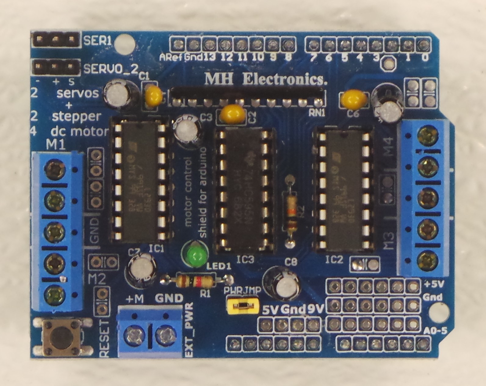
I found that the best way (lowest cost and easiest to assemble) for driving multiple solenoids is to use the L293D Motor Driver Shield. This shield was originally designed by Adafruit, but was discontinued in 2014. (Adafruit now sells version 2 of this shield, which uses a TB6612 MOSFET instead of the L293D). However, there are a lot of other places that still sell knock-off/generic versions of the L293D Motor Shield, some of which sell this part for less than $2.
The Motor Shield was intended to drive 4 motors (each one forward or backward) or 2 servo motors. The forward/backward is possible because each motor terminal can send the positive voltage to either the A side or the B side.
I have found that it is possible to take advantage of the motor forward/backward capability and use this Shield to drive up to 8 solenoids. The Motor Shield was probably not intended to be used this way, but I have found that it works.
If your read the specs of the L293D Motor Shield, it will tell you that it can take up to 24 Volts DC input. That may have been true with the original ones. However, when I took one of these cheap, generic Shields, and tried (for a different application) hooking up 24V to the power in, I blew up one of the capacitors. When I looked more closely at the capacitors, I saw that it was rated for only 16V. Oh well, I guess you get what you pay for. These shields work just fine for the 12V DC needed for these 12V solenoids.
The picture below shows how the solenoids are wired into the Motor Shield. One wire from each solenoid is tied to the GND terminal (the middle of the 5 terminals on either the left or right side). The other wire from each solenoid is tied into the appropriate motor terminal (M1A, M1B, M2A, M2B, M3A, M3B, M4A, or M4B). For the purpose of this project, each of these motor terminals will be referred to as a “Channel” numbered 0 through 7. (M1A is channel 0, M1B is channel 1, and so on.)
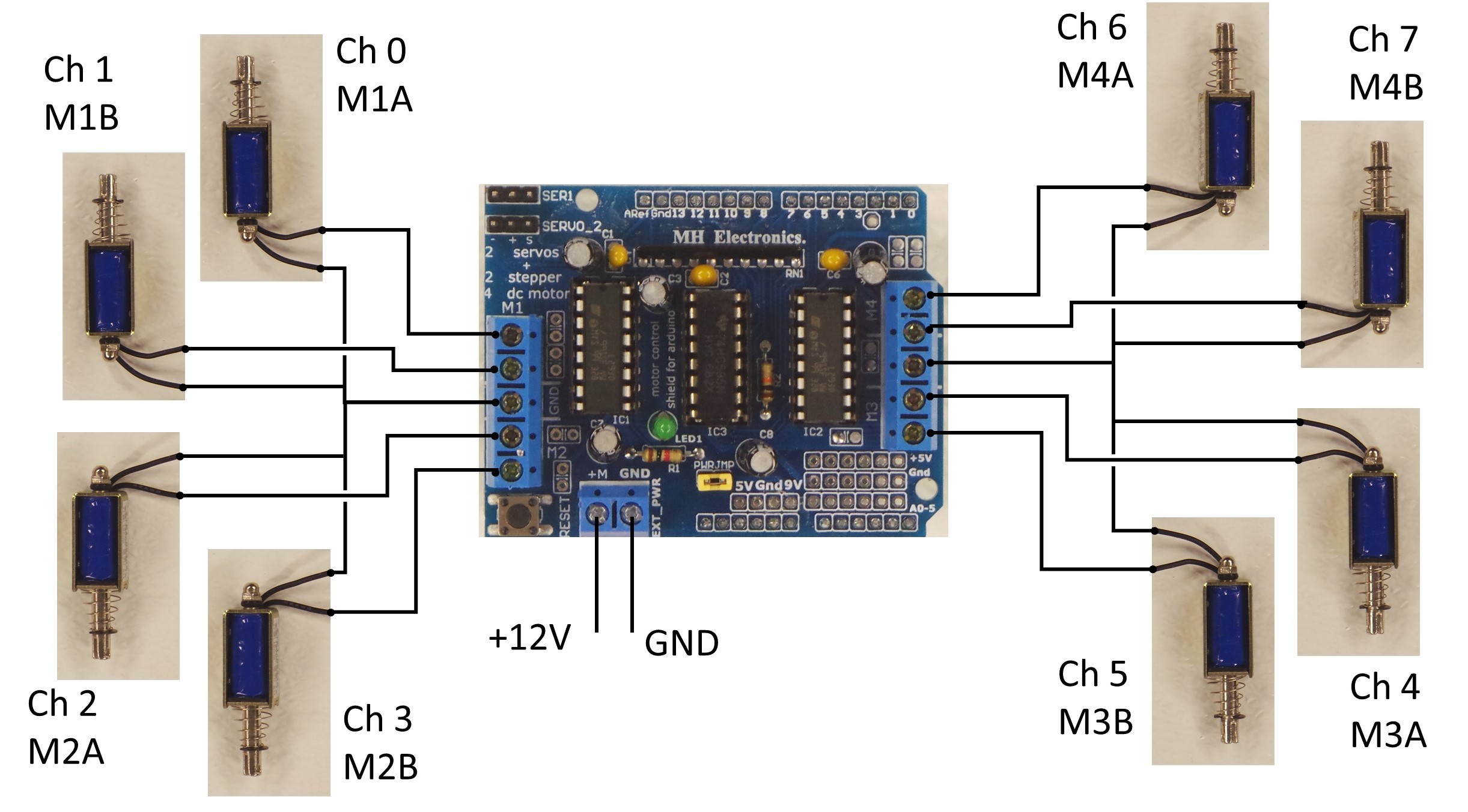
A picture of the Motor Shield with 8 solenoids is shown below:

Here is a video which shows the Motor Shield firing the 8 solenoids sequentially.
Arduino source code for firing the solenoids via the Motor Shield is found here. Note that in order to have the Arduino fire the solenoids in order, as shown in the video , the #define HARDWARE_TEST needs to be set to 1, as per the code comments.

Controlling Multiple Motor Driver Shields
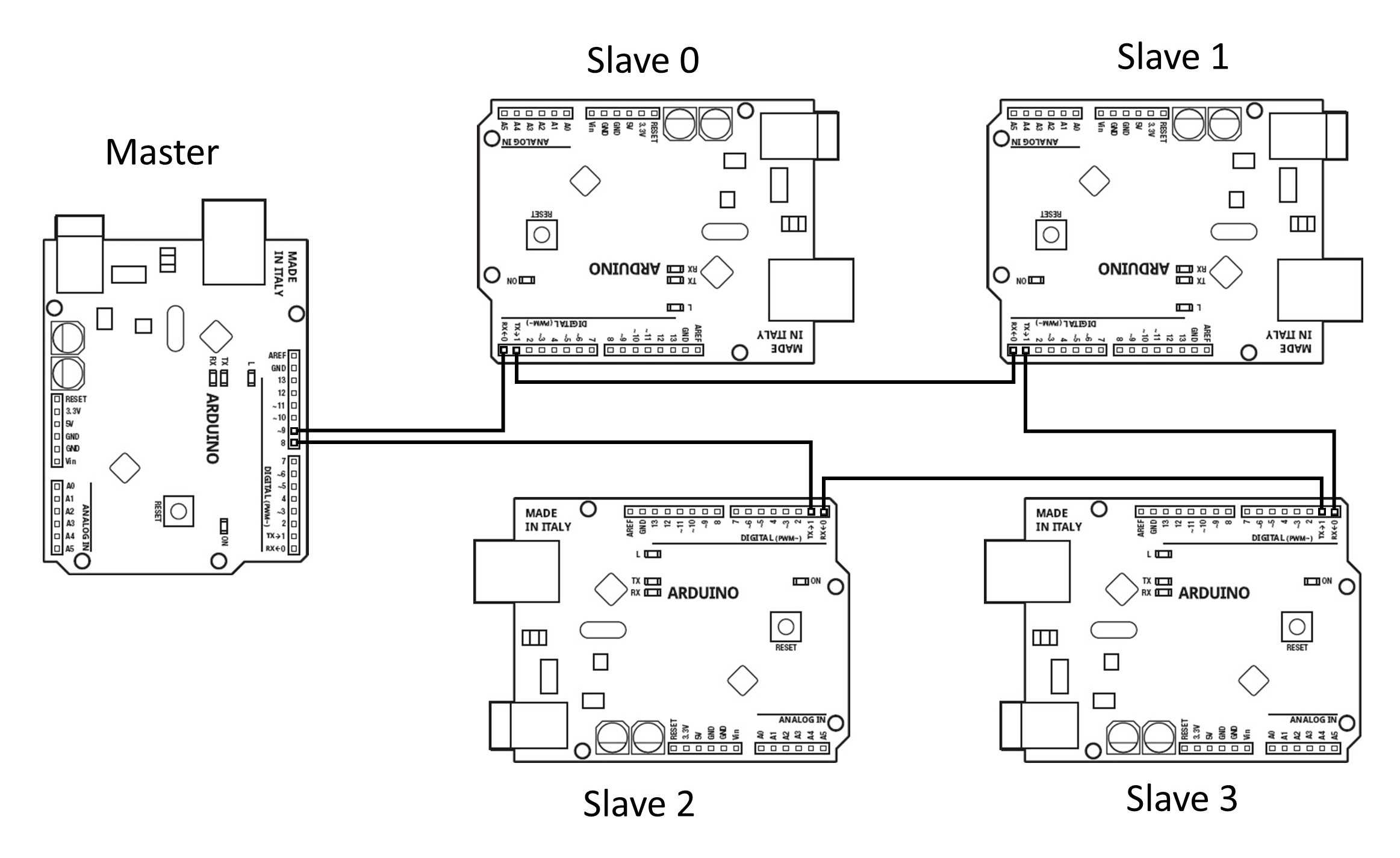
You’re probably wondering how I can drive 25 solenoids, when the Motor Driver Shield supports only 8. The answer is that I use multiple Arduino Uno’s each with a separate Motor Shield. Each of these Uno’s is a Slave, recieving commands to drive the solenoids via Serial. A separate Arduino Uno is the Master, controlling all of the Slaves.
Multiple Slaves can be controlled by one master by wiring the TX of the Master to the RX of Slave 0, the TX of Slave 0 to the RX of Slave 1, and so forth. An example of wiring one Arduino Master to control multiple Arduino Slaves is shown below.

Sometimes, it may be desirable for the Master Arduino Uno to control the Slaves via pins other than the built-in Serial TX/RX pins (pins 0 and 1). In that case, any other pins can be used to control the Slave Devices via the SoftwareSerial library. The example below shows the Master using pins 8 and 9 with the SoftwareSerial library.
Note that the robotic xylophone version 2.0 (utilizing SPI Flash as the Data Storage) has the Master using pins 8 and 9 with the SoftwareSerial library, while version 2.1 (utilizing an SD Card as the Data Storage) uses the standard serial pins.
In order for this Master/Slave arrangement to work, each Slave needs to recieve a message, process the message, and then transmit the same message to the next Slave. When each Slave transmits the same message that it recieves, then all Slaves in the line will be able to see the same message from the Master.
Serial messages transmitted by the Master are of the form:
<aabb>
where aa and bb are bytes in hexadecimal format. aa is the address of the slave, and bb is a bitmask corresponding to the channels/solenoids on the Motor Shield which are to be fired.
The address of the Slave is set in the Arduino program code via the #define DEVICE_ADDRESS line.

For example, to energize the solenoids on channels 2, 4, and 7 on Slave 1, the Master needs to send the message:
<0194>
Note that 94 in Hexadecimal is 10010100 in Binary. The left-most bit corresponds to channel 7, while the right-most bit corresponds to channel 0.
While a song is being played on the xylophone, the Master is continually sending commands for all of the Slaves. So for example, at one instant, the Master might send the message:
<0004><01A0><0255><0300>
which would mean:
- On Slave 0, energize channel 2
- On Slave 1, energize channels 5 and 7
- On Slave 2, energize channels 0, 2, 4, and 6
- On Slave 3, de-energize all channels
Source code for the Master/Slave Motor Shield functions is found here on Github. The program L293DBoardSerial.ino is the program that is loaded into each of the Slaves. (Make sure to set the DEVICE_ADDRESS appropriately, and that HARDWARE_TEST is set to 0.)
The programs L293DMasterTest and L293DMasterLcdRotary are test programs that are used demonstrate the Master/Slave functionality. L293DMasterTest.ino is a bare-bones sketch that shows in the Master sending commands to one or more Slaves. L293DMasterLcdRotary.ino includes the code for the LCD and Rotary Encoder, allowing one to use this interface to select the solenoid to be energized.
Below is shown my Test Assembly, with 1 Slave connected to a Master, and the LCD and Rotary Encoder.

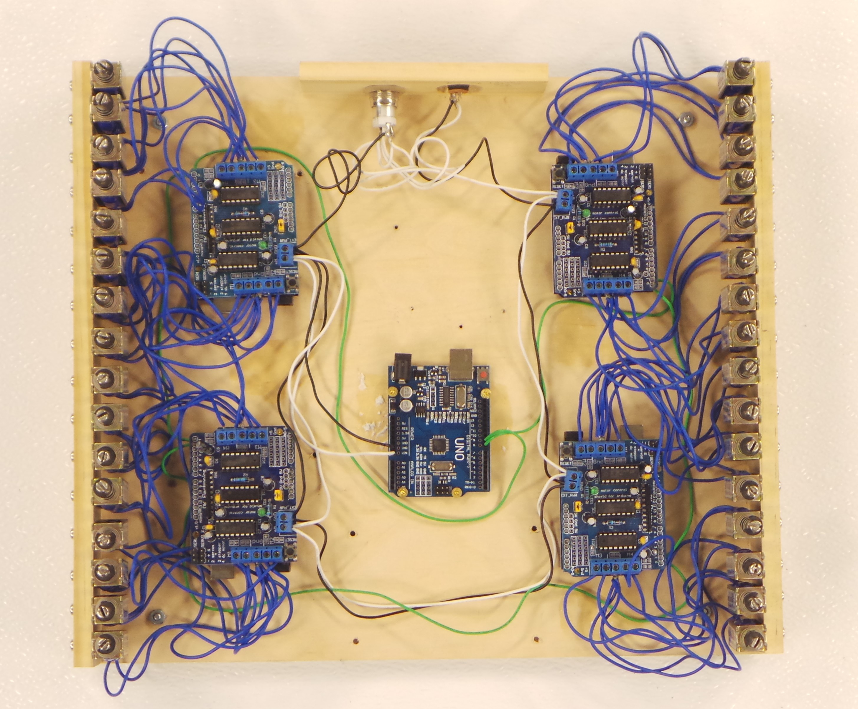
Here is another test setup that I made, where one Arduino Master controls 4 Slaves, and a total of 32 Solenoids.
Next: Data Storage
