
This page shows instructions for version 2.1 of the robotic xylophone which uses an SD Card for the data storage. Instructions for version 2.0, using SPI Flash, are here.
The four sides of the enclosure and the runners are assembled using wood glue, as follows:
Glue “G” and “H” pieces onto “A” as shown below. All “G” and “H” pieces should be 1/4″ (the thickness of the boards and plywood) from the edge. Use a scrap piece of the 5-1/2″ x 1/4″ board, and a scrap piece of the plywood, to mark the exact thickness. “G” and “H” pieces should be approximately centered on their respective edges. You will need to use clamps to secure the “G” and “H” pieces to the board until the glue dries.

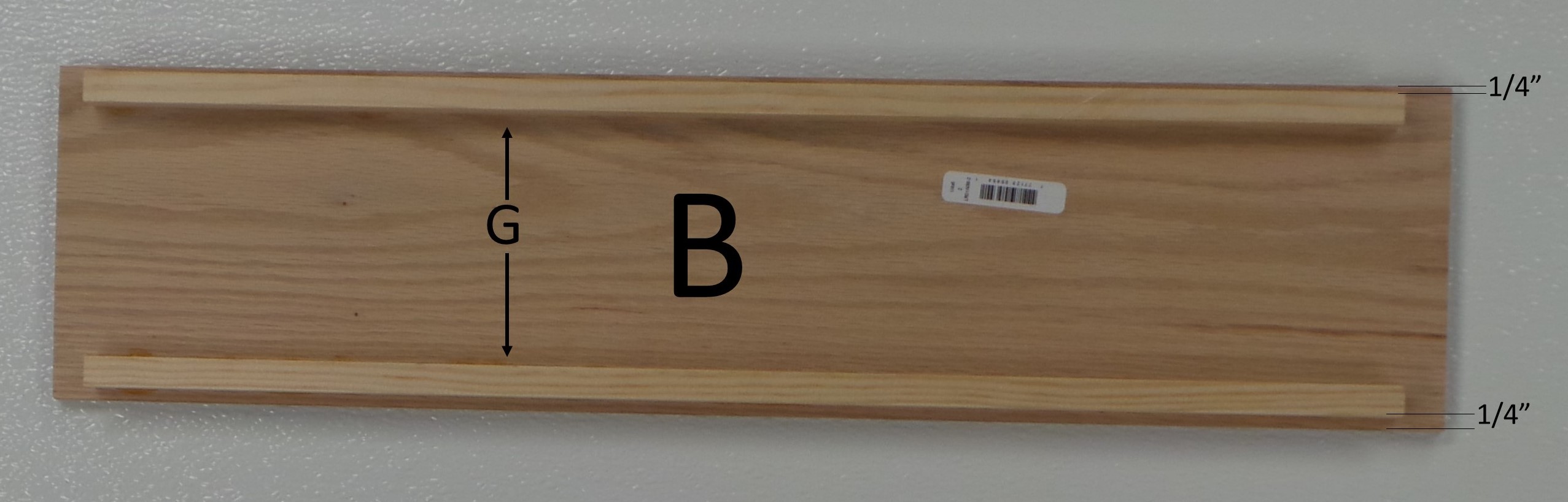
Glue “G” pieces onto “B”, 1/4″ from edge.
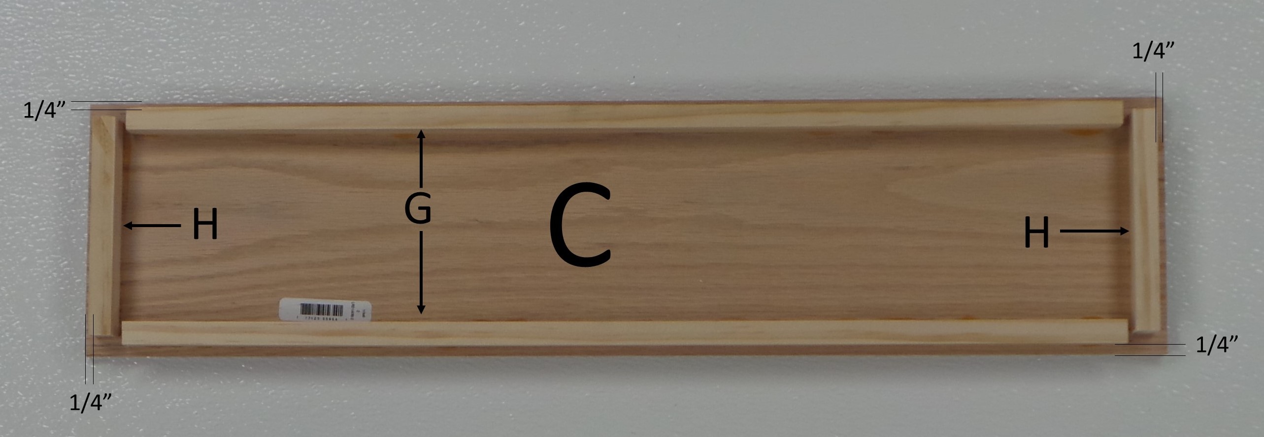
Glue “G” and “H” pieces onto “C”, 1/4″ from edge.
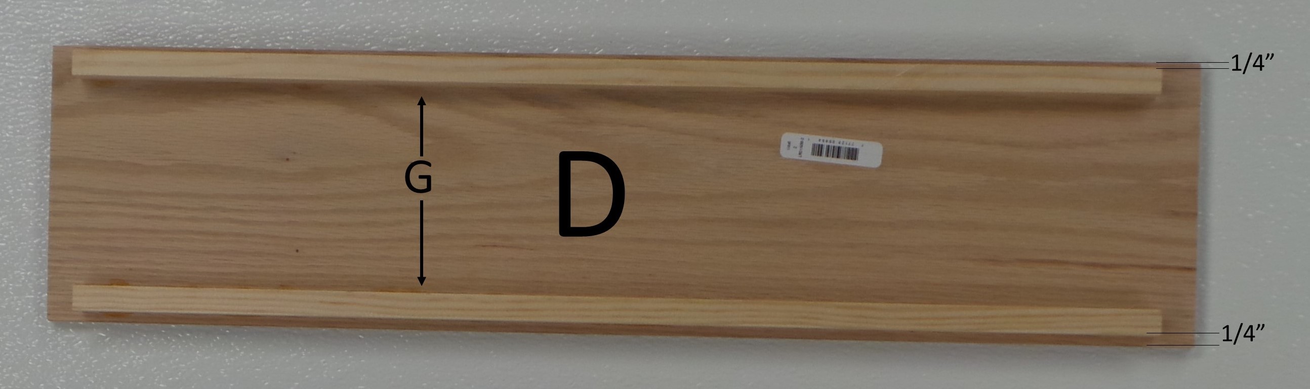
Glue “G” pieces onto “D”, 1/4″ from edge. Piece “D” will be identical to piece “B”
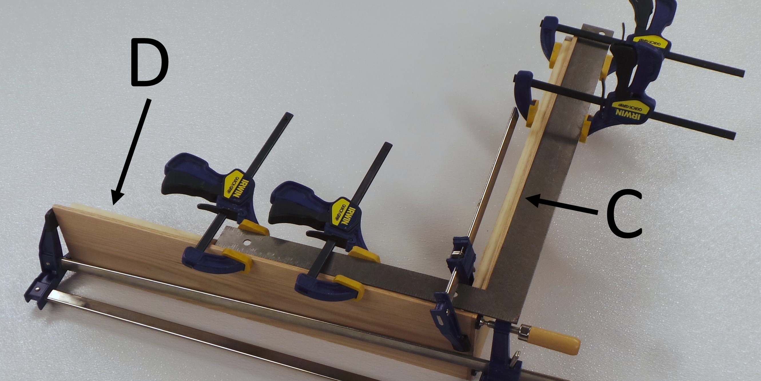
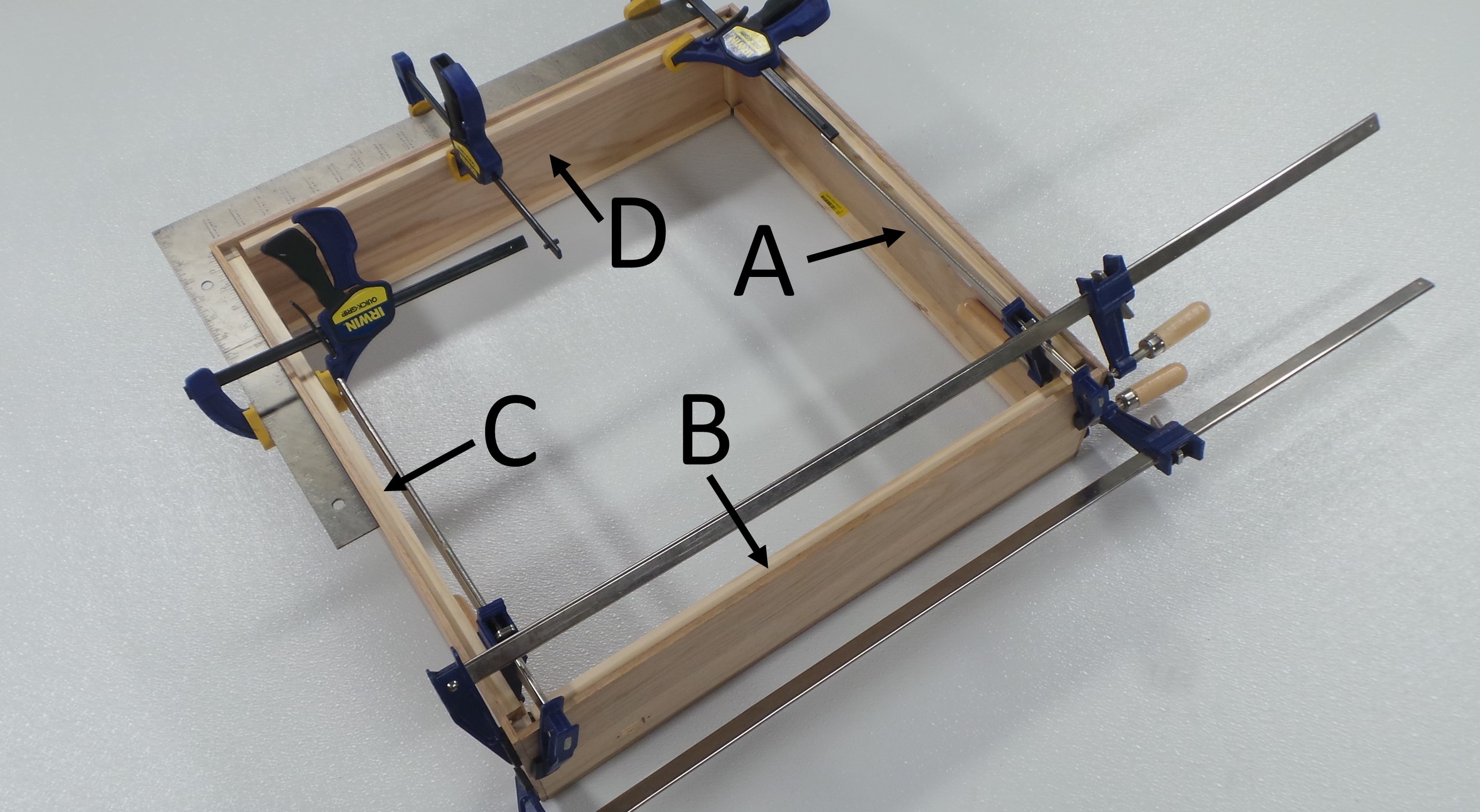
Use clamps and a carpenter’s square to glue “C” and “D” together at the corner.
After the glue for the “C-D” corner dries, use the same clamps and square to glue “A” and “D” together at the corner.
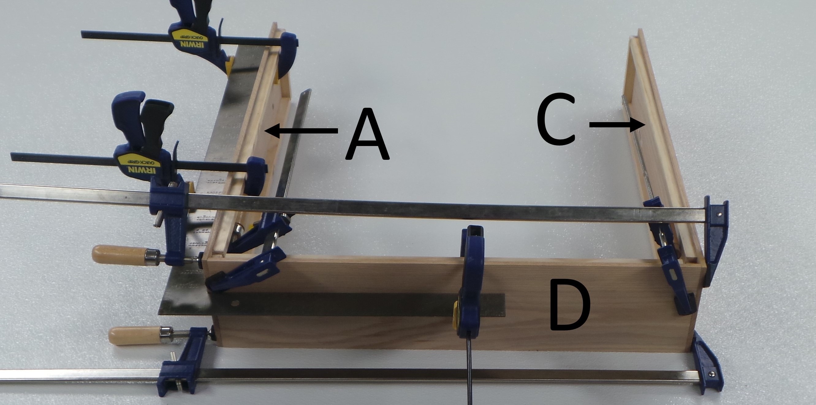
After the glue for the “A-D” corner dries, glue piece “B” onto “A” and “C”. Again, clamp the joint, and use a carpenter’s square to keep the corners at a right angle.
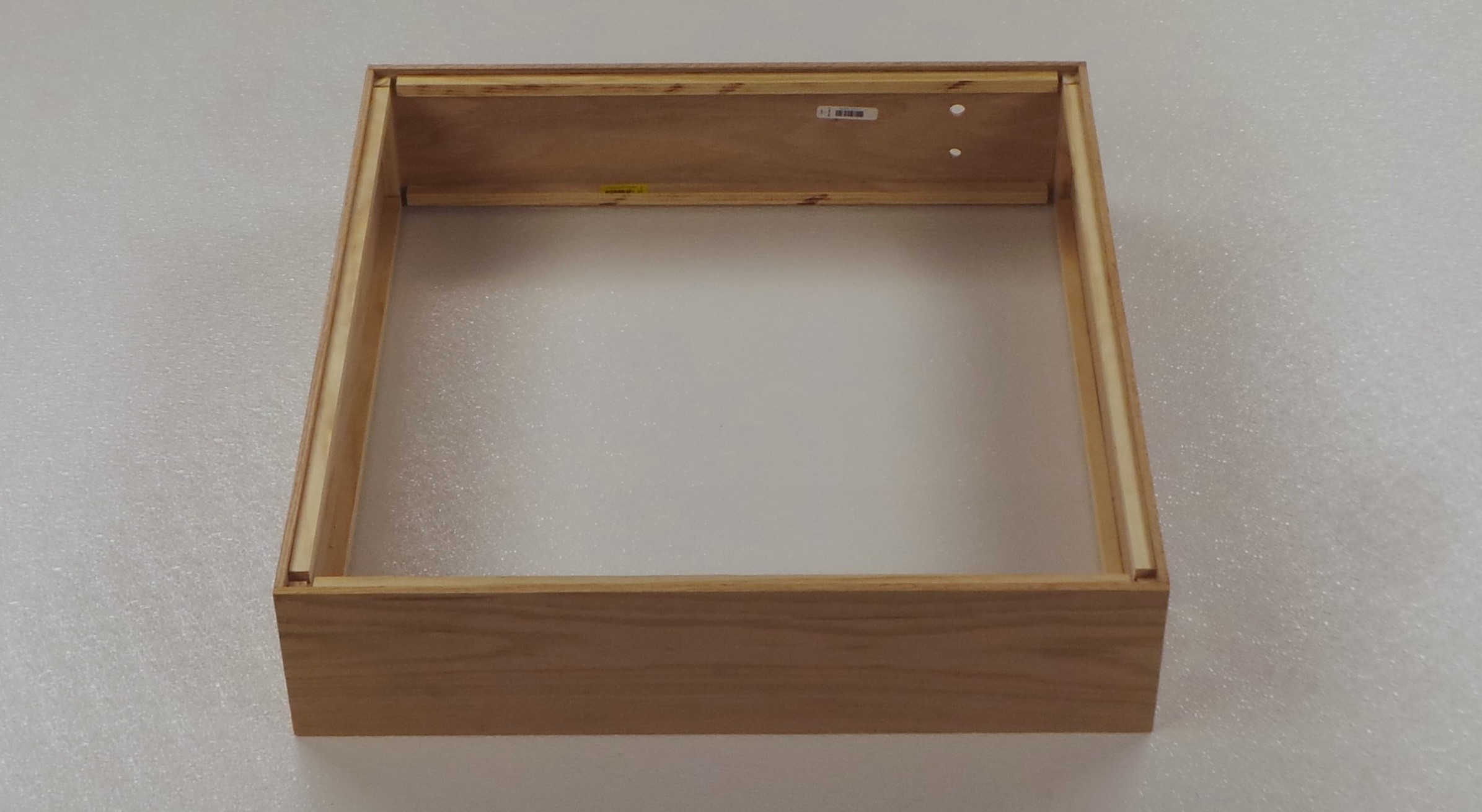
After all glue has dried, remove the clamps. The four sides of the enclosure will look similar to below.
The Runners are glued as follows:
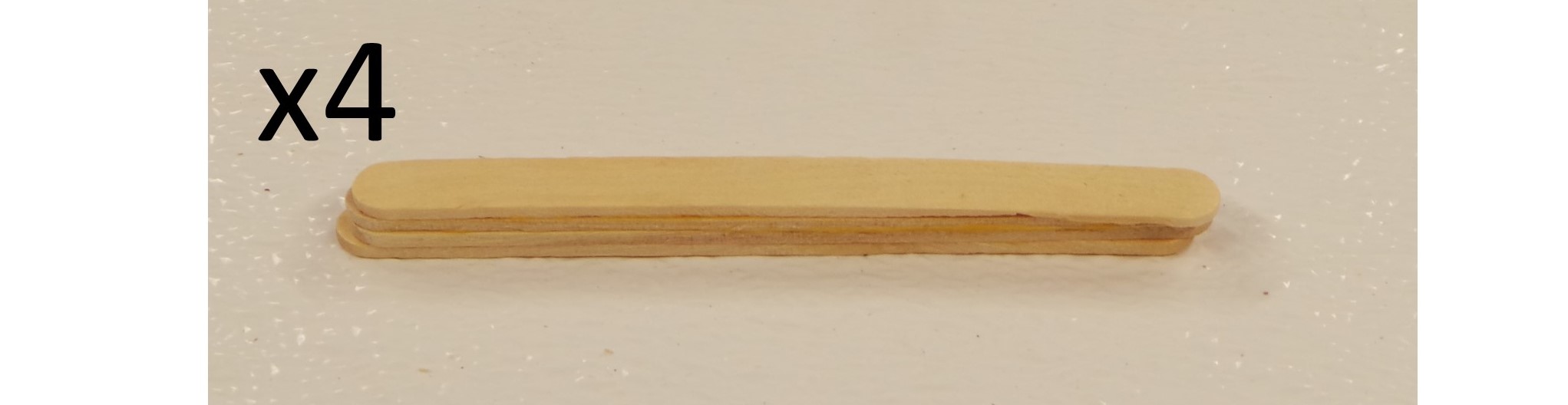
Glue four (4) of the Popsicle sticks together, top to bottom. Do this 4 times, utilizing all 16 of the Popsicle sticks.
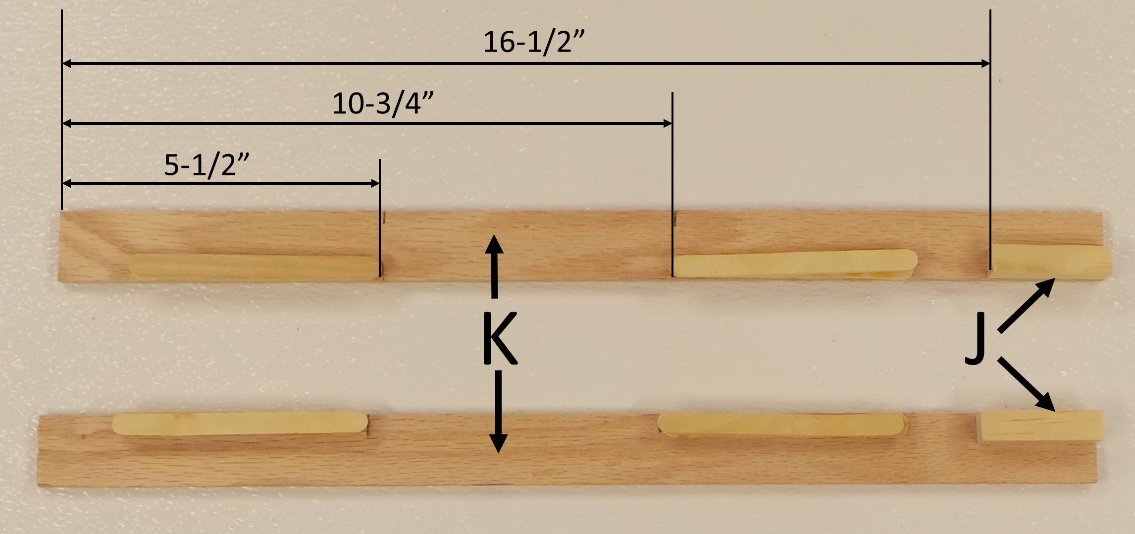
Glue the 4 Popsicle Stick Stacks and 2 pieces “J” onto the Runner pieces “K” as shown below. Make sure that the two sides are mirror images of each other. The two Runners will be attached to the main part of the enclosure and allow the Window to slide opened and closed.
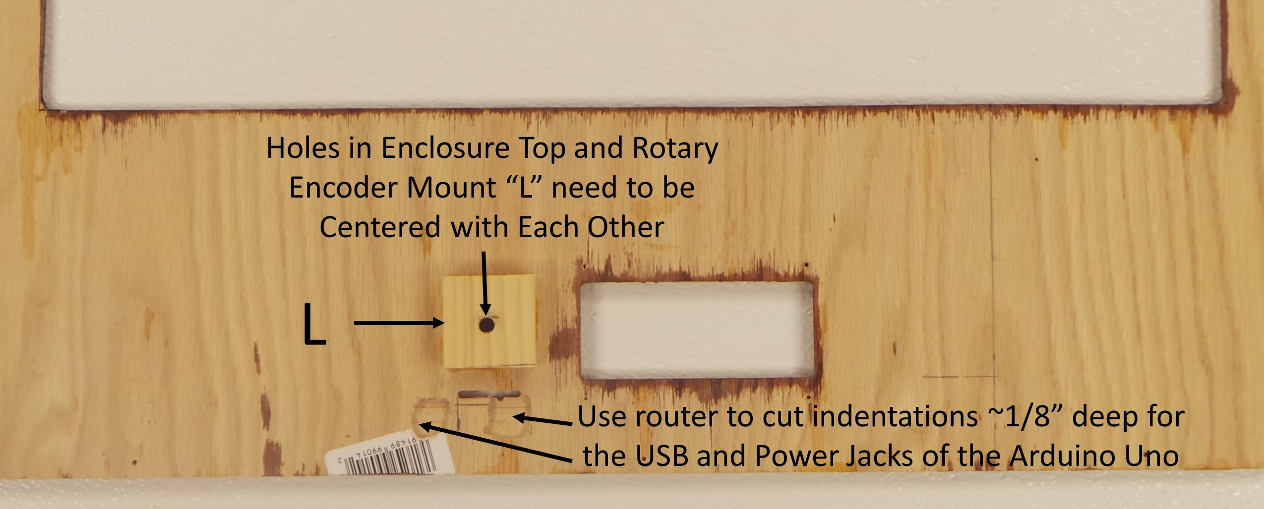
Use a router to cut indentations approximately 1/8″ deep, near the SD card slot as shown below. These will be for the Power and USB Jacks of the Arduino Uno. Note that these Jacks will not be exposed. Attach the Data Logger Shield to the Arduino, and insert the SD card. Place the assembly flush with the encosure top, and insert the SD Card into the slot. Trace the approximate positions of the Power and USB Jacks. Then use the Router to cut the indentations. Make sure that you cut the indentations before gluing on the Rotary Encoder Mount.
Glue the Rotary Encoder Mount piece “L” to the back of the Enclosure Top piece “E” as shown below. Make sure that the 1/4″ diameter hole in “L” is centered with the 5/8″ diameter hole in “E”.
Next: Finishing
