
The User Interface for the robotic xylophone is a Character LCD with I2C and a KY-040 Rotary Encoder. If you are into the latest and greatest display and control devices for Arduino, these are comparatively very old-fashioned. But they will do the job that is needed, are very low cost, and can be connected to the Arduino with no soldiering or other additional components. In fact, if you want to do any Arduino project that has a local display and control, I would submit to you that there is nothing else out there that is both as cheap, and easy to assemble, as these two components. Furthermore, with the libraries and code examples I have found on the Internet, it is extremely easy to program the Arduino to use the I2C LCD and Rotary Encoder.
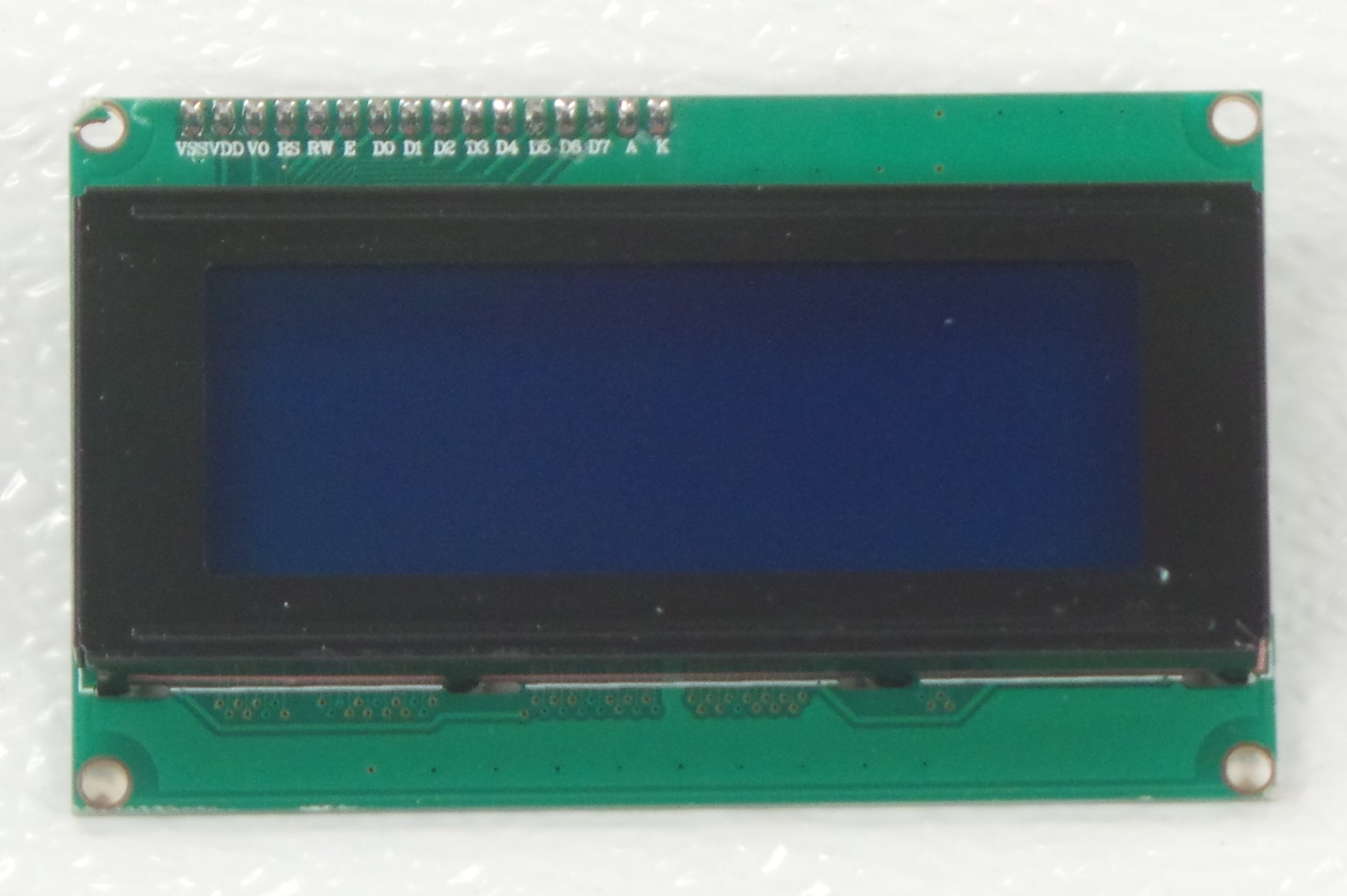
The Character LCD typically comes in two sizes: 16×2 (2 rows each with 16 characters) and 20×4 (4 rows each with 20 characters). It also comes in two colors: Blue Background with Cyan/White Text and a Greenish-Yellow Background with Black Text. Yes, I know that there are other sizes and colors out there. But these are the standard ones, and these are also the ones that I have found for the lowest price – as low as $2 for the 16×2 size, and $5 for the 20×4 size. I recommend getting the LCD with the I2C board already soldiered because this is so much easier than trying to soldier all the pins on the LCD yourself.
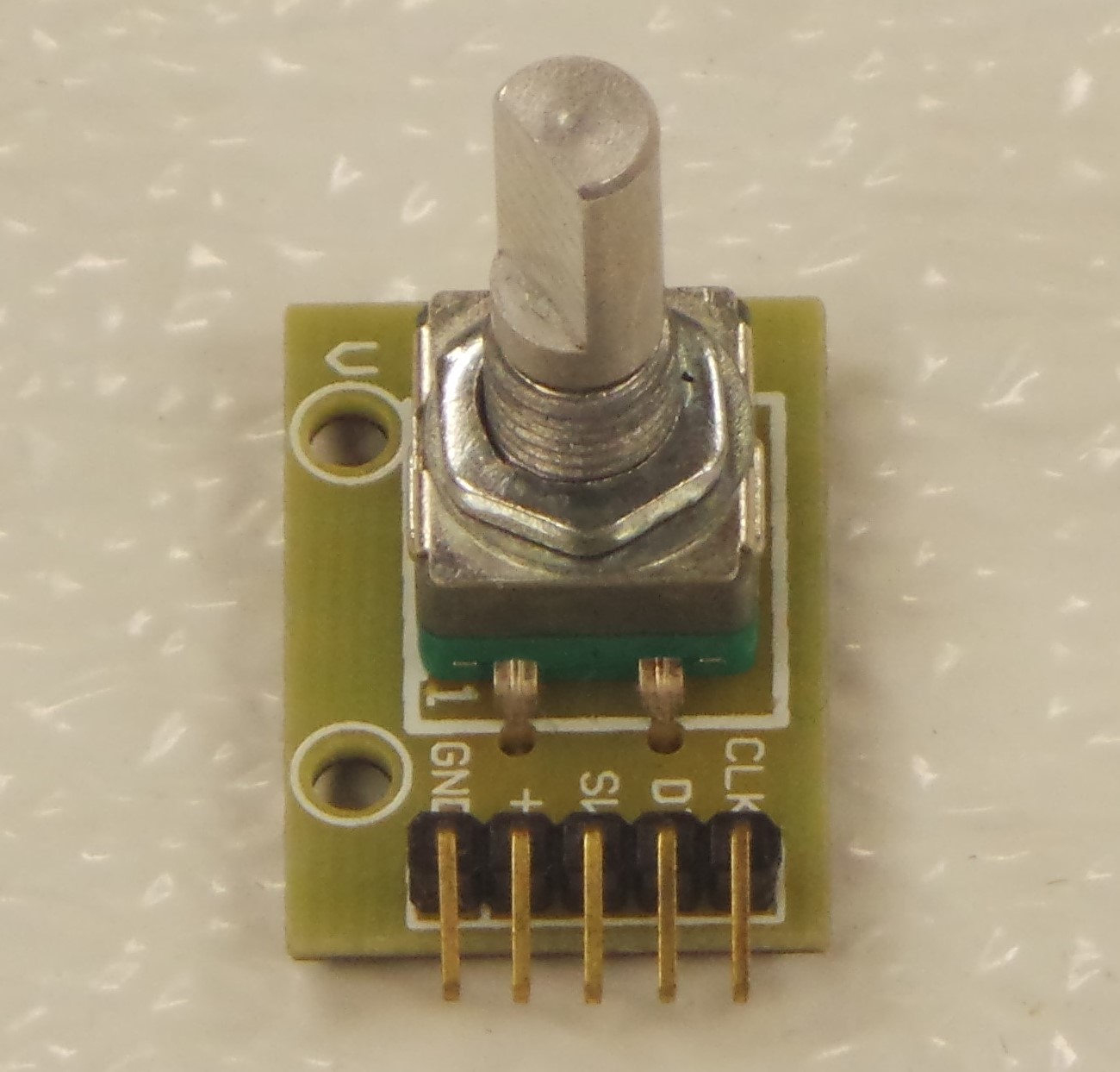
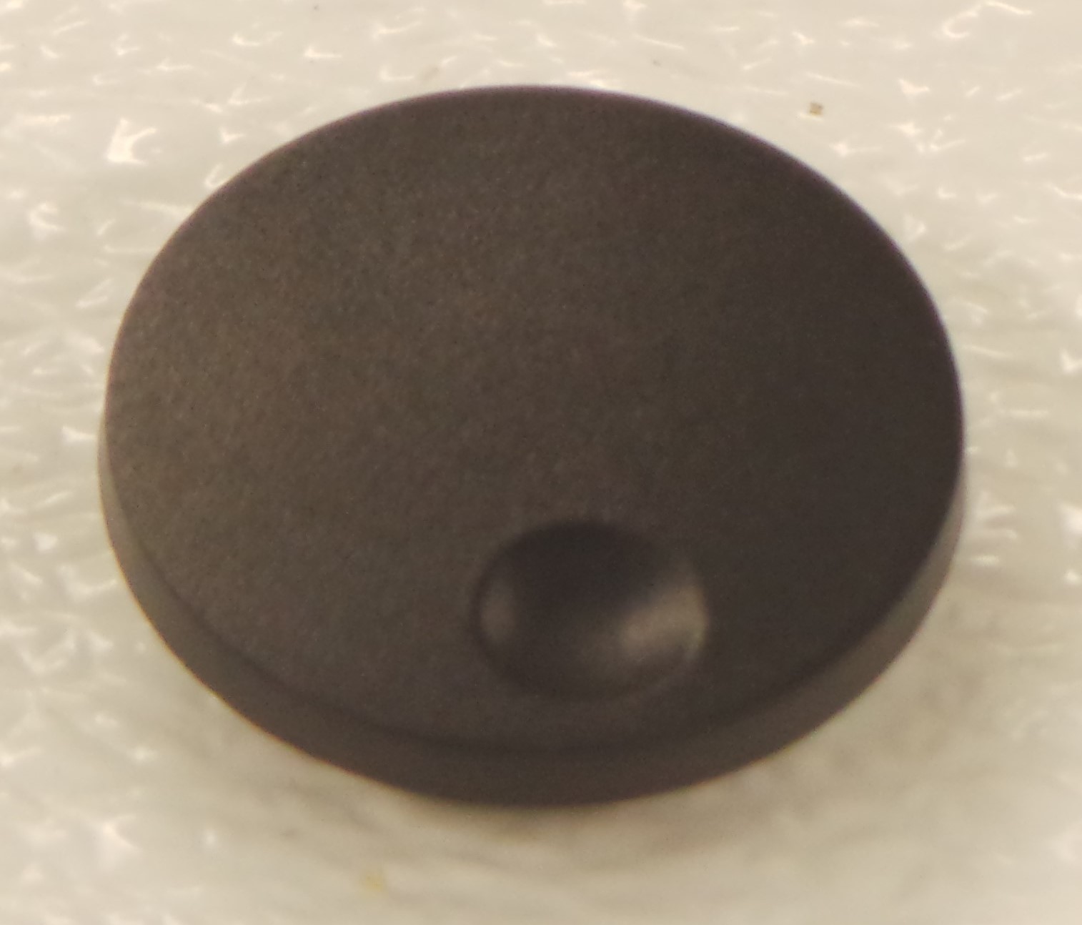
The Rotary Encoder is very useful for control because it can be turned left or right, and can be pressed. Essentially, it can do the function of 3 separate push-buttons. The Rotary Encoder is especially suited for creating a navigable menu: turn it left or right to scroll through a list of options, and press it down to select. I have found a software example that detects and debounces Rotary Encoder ticks very well. I have also found a software library does the pushbutton functions very well, that can detect the difference between a button single-click, double-click, and long press (just like with your computer mouse.) I have seen the KY-040 Rotary encoder for as little as $0.50. I recommend using the Adafruit Scrubber Knob because it makes the rotary encoder so much easier to turn and press than the smaller knobs that often come with the part. I have not found any good place to get this, other than the Adafruit website.
Wiring these components to the Arduino is very simple. The LCD is attached to the Arduino pins as follows:
- GND on LCD to GND on Arduino
- VCC on LCD to +5V on Arduino
- SCL on LCD to SCL (pin A5) on Arduino
- SDA on LCD to SDA (pin A4) on Arduino
The Rotary Encoder is attached to Arduino pins as follows:
- CLK to Arduino Pin 2
- DT to Arduino Pin 3
- SW to Arduino Pin 4
- VCC to Arduino Pin 5
- GND to Arduino Pin 6
Below are shown a schematic wiring digram and pictures of the components wired together.


Both the LCD and Rotary Encoder are connected using Male-to-Female jumper wires, which are available in lengths of 10cm, 20cm, or 30cm.
If you’re wondering why VCC and GND on the Rotary Encoder are attached to I/O pins on the Arduino, instead of the +5V and GND pins, it’s because I am cheating a little here. In the Arduino software, Pin 5 will be set to HIGH, and Pin 6 will be set to LOW to provide the 5V differential. I can do this, because the current draw from turning or clicking the Rotary Encoder is less than the 40mA maximum current allowed on the I/O pins. Using the I/O pins for +5V and GND keeps the Arduino’s actual 5V and GND pins available for other peripheral devices.
Example code that demonstrates using the L2C LCD and Rotary Encoder is available on Github. Feel free to use this code not just for the robotic xylophone, but for any other Arduino project that utilizes these components.
Next: Mechanism
