
Once the enclosure is built, and the xylophone and mallet assembly are mounted, the electronics are assembled as follows:
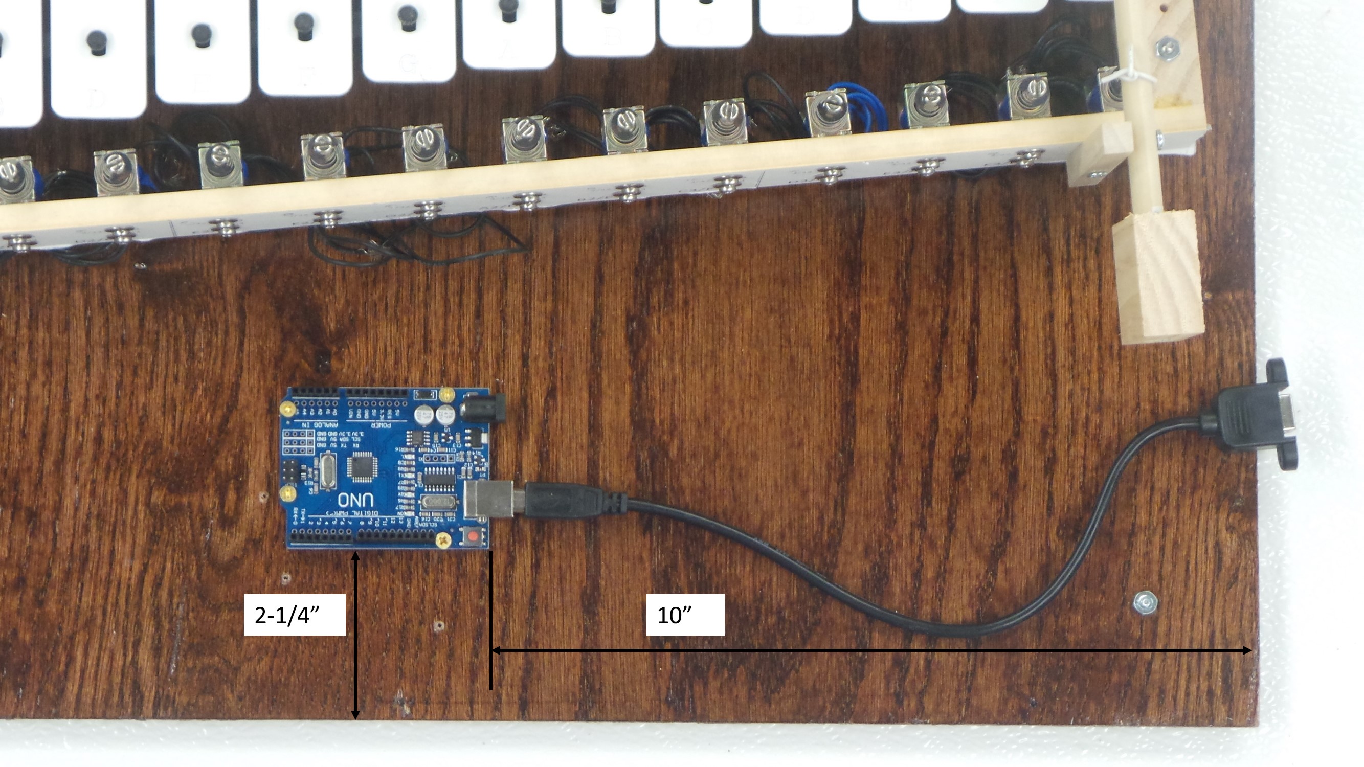
Step 1: Use four (4) #4 x 3/8″ wood screws to attach an Arduino Uno as shown below. The Arduino should be approximately 10 inches from the right side of the base, and 2-1/4″ from the front of the base. Verify that the Arduino is in a good position for the USB Panel Mount to reach from the side of the enclosure to the Arduino. This Arduino will be the “Master” Arduino because it controls everything else.
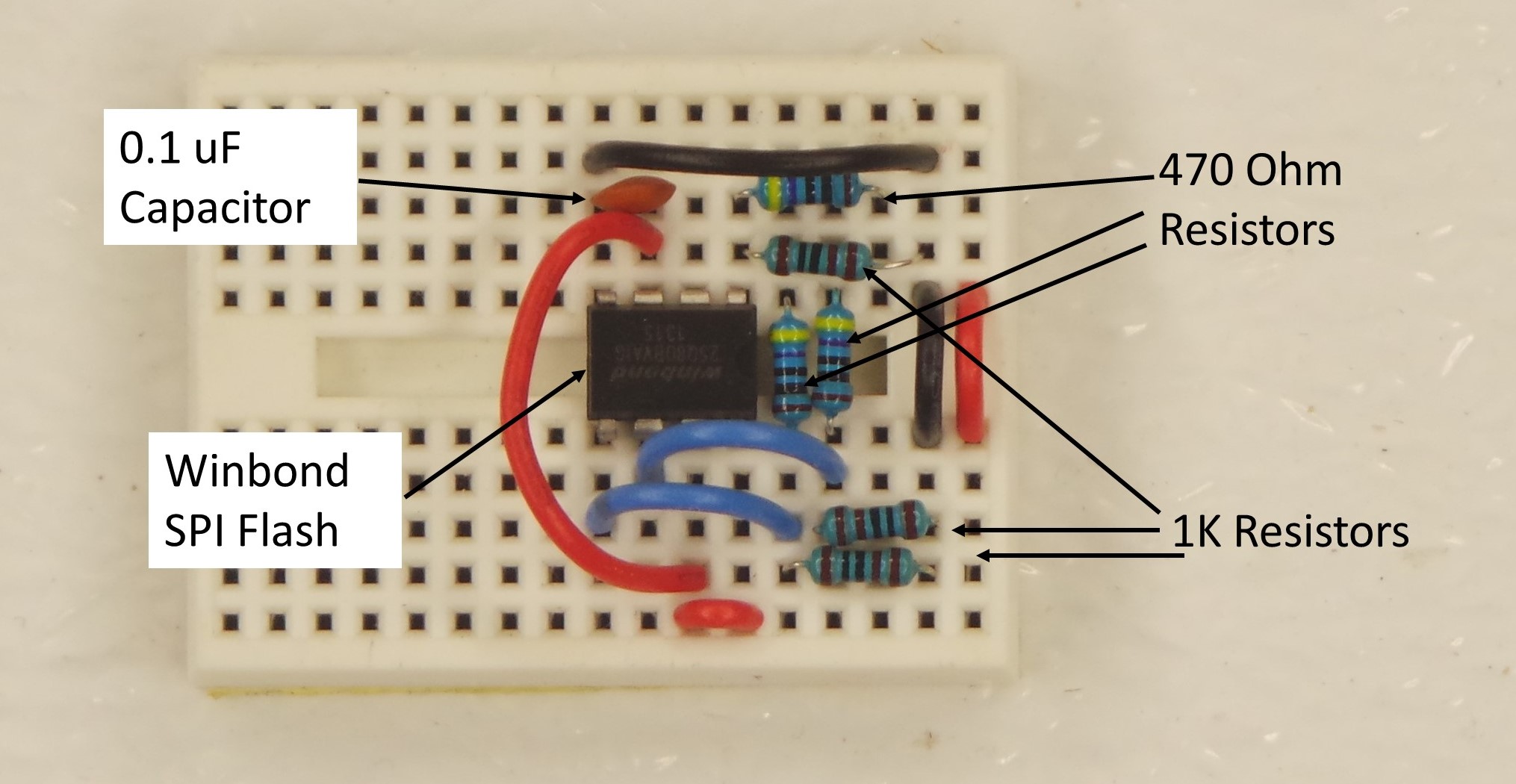
Step 2: Place the components for the Winbond SPI Flash Memory onto the SYB-170 Solderless breadboard, as shown below. In addition to the Flash Memory chip, you will need 3 1K Resistors, 3 470 Ohm Resistors, one 0.1 uF Capacitor, and some short pieces of the 22 AWG hook-up wire.
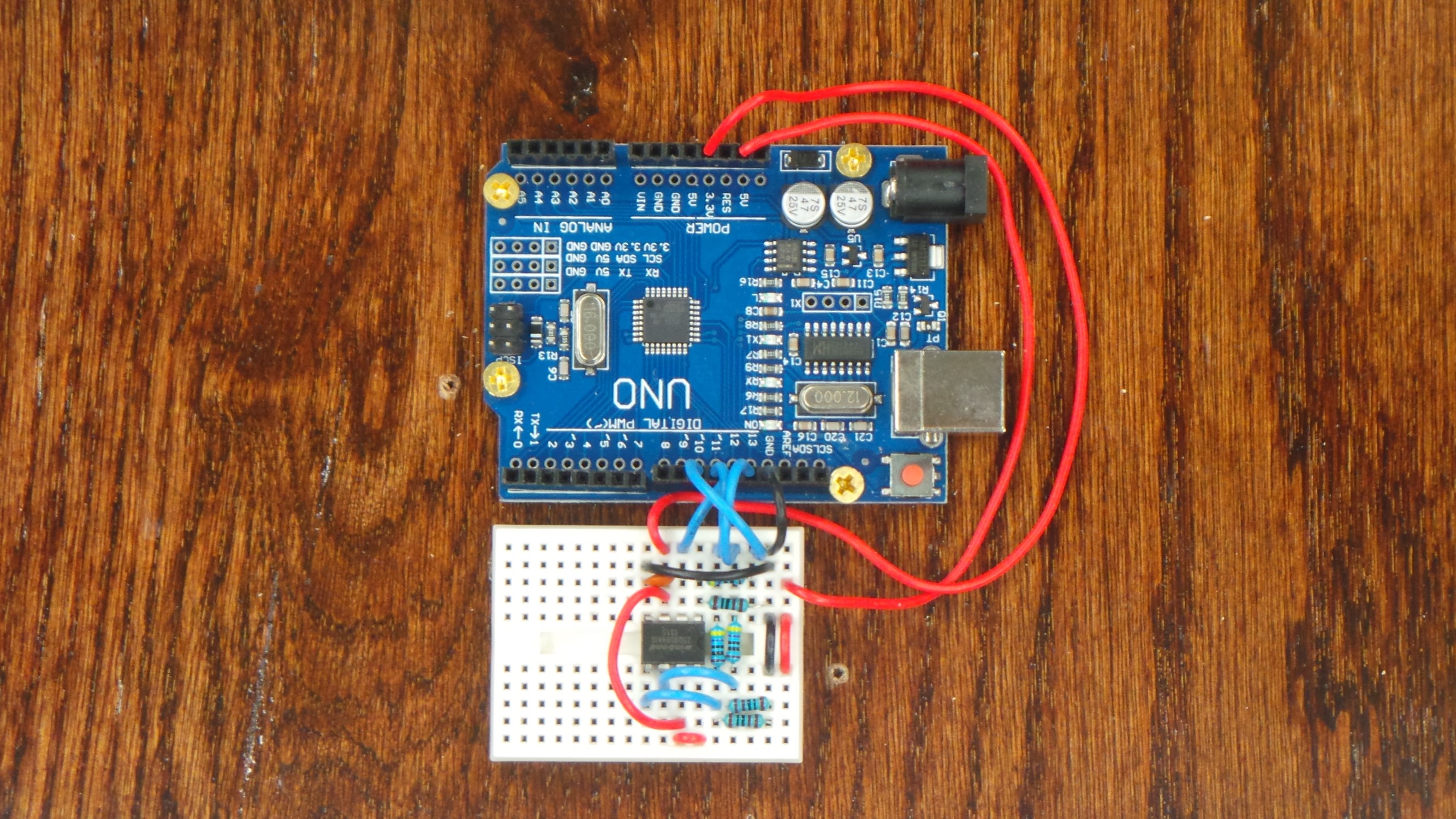
Step 3: Using the adhesive back of the breadboard, affix it adjacent to the Arduino as shown below. Connect the pins 10, 11, 12, 13,5V, 3.3V, and GND of the Arduino to the breadboard as shown here.
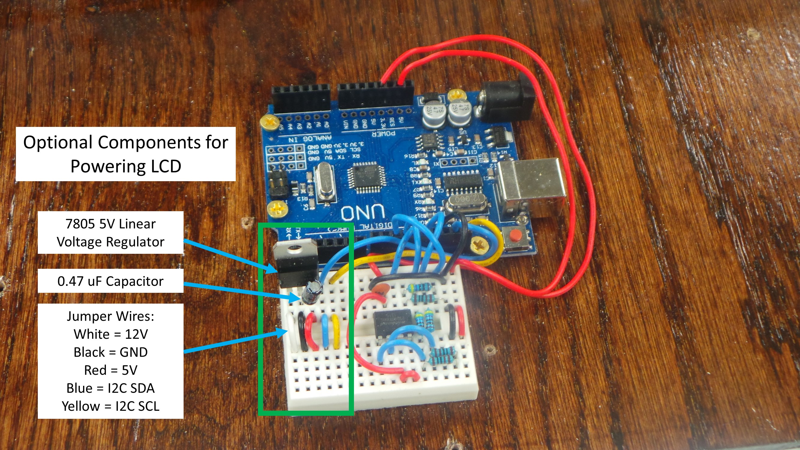
Step 4 (Optional): In some cases, I have found that the generic brand Arduino Uno’s do not have enough power for the 20×4 Character LCD, particularly when there are a lot of other components to be attached. If you want the LCD to be powered separately from the Arduino, you may add a 7805 5V Linear Voltage Regulator and 0.47 uF Capacitor to the breadboard as shown below.
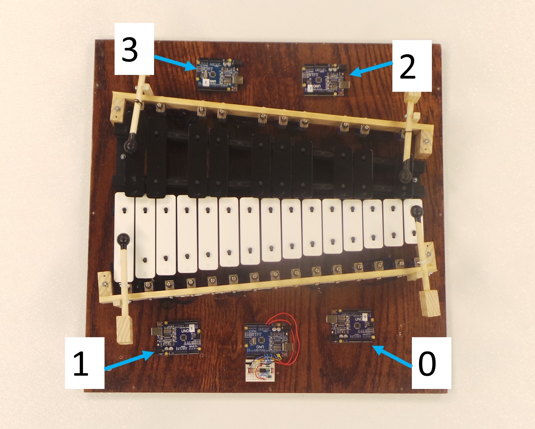
Step 5: Label the four remaining Arduino Uno’s with the numbers 0, 1, 2, and 3 as shown below. These will be referred to as “Slave” Arduino boards, because they will receive commands from the “Master” Arduino.

Step 6: Download the program “L293DBoardSerial.ino” into each of these labeled Arduino’s. Prior to downloading, change the #define DEVICE_ADDRESS to whatever is labeled on the Arduino. In short, this program controls the L293D Motor Driver board, and it fires the solenoids according to Serial messages that it recieves. See the Motor Driver Tutorial and Software page for more details on this program. This program is available on Github.

Step 7: Secure the four labeled Arduino boards to the base as shown below. Use four #4 x 3/8″ wood screws for each Arduino board.
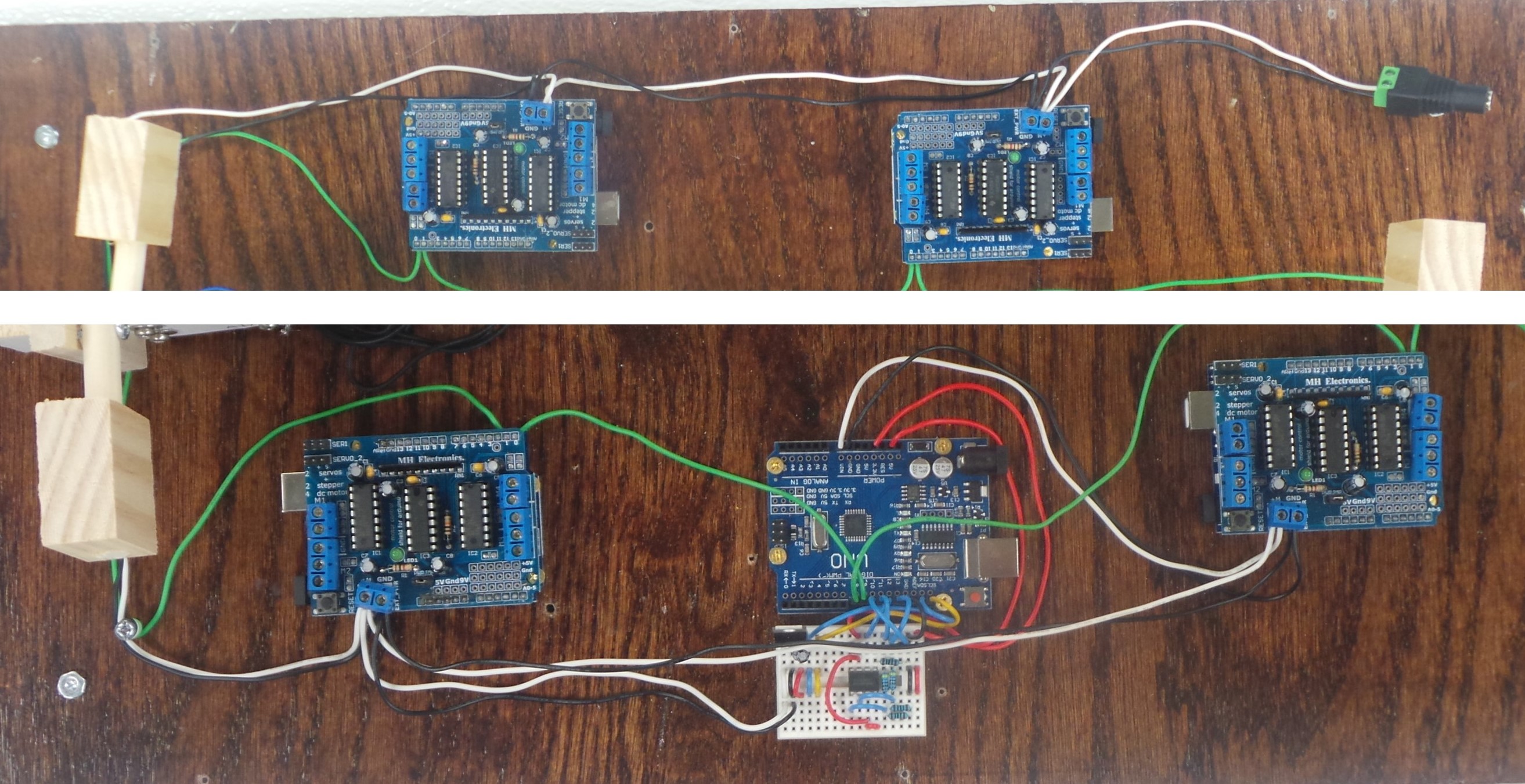
Step 8: Using 22 AWG hook-up wire, attach the 5 Arduino boards as shown below:
- Master Pin 9 (SoftwareSerial TX) to Slave 1 Pin 0 (RX)
- Slave 1 Pin 1 (TX) to Slave 3 Pin 0 (RX)
- Slave 3 Pin 1 (TX) to Slave 2 Pin 0 (RX)
- Slave 2 Pin 1 (TX) to Slave 0 Pin 0 (RX)
- Slave 0 Pin 1 (TX) to Master Pin 8 (SoftwareSerial RX)
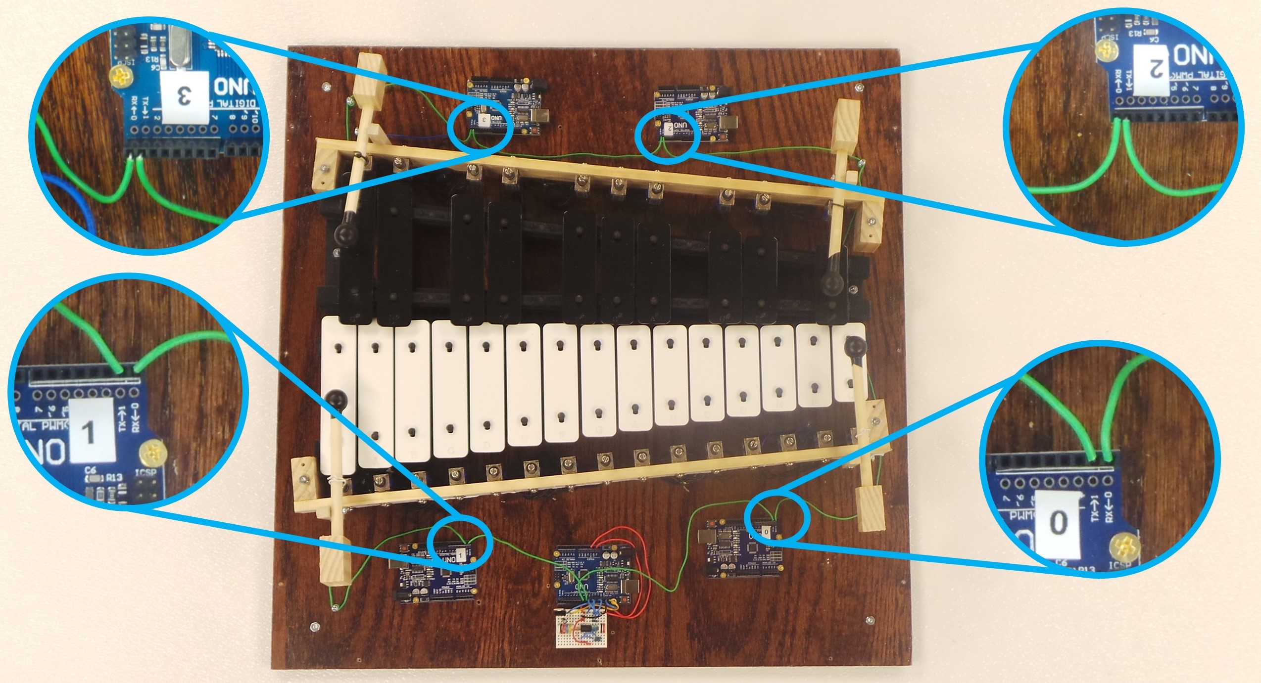
Note that the SoftwareSerial library is part of the Master Arduino’s program. This allows the Arduino Uno to use pins 8 and 9 as an additional Serial Port.
The above arrangement works because the “L293DBoardSerial” program, which is running inside each of the Slave Arduino boards, always transmits the same serial messages that it receives. So when the Master Arduino sends a command via the SoftwareSerial TX pin, this command gets passed onto each of the Slave Arduino boards. See the Motor Driver Tutorial page for more details on this architecture.
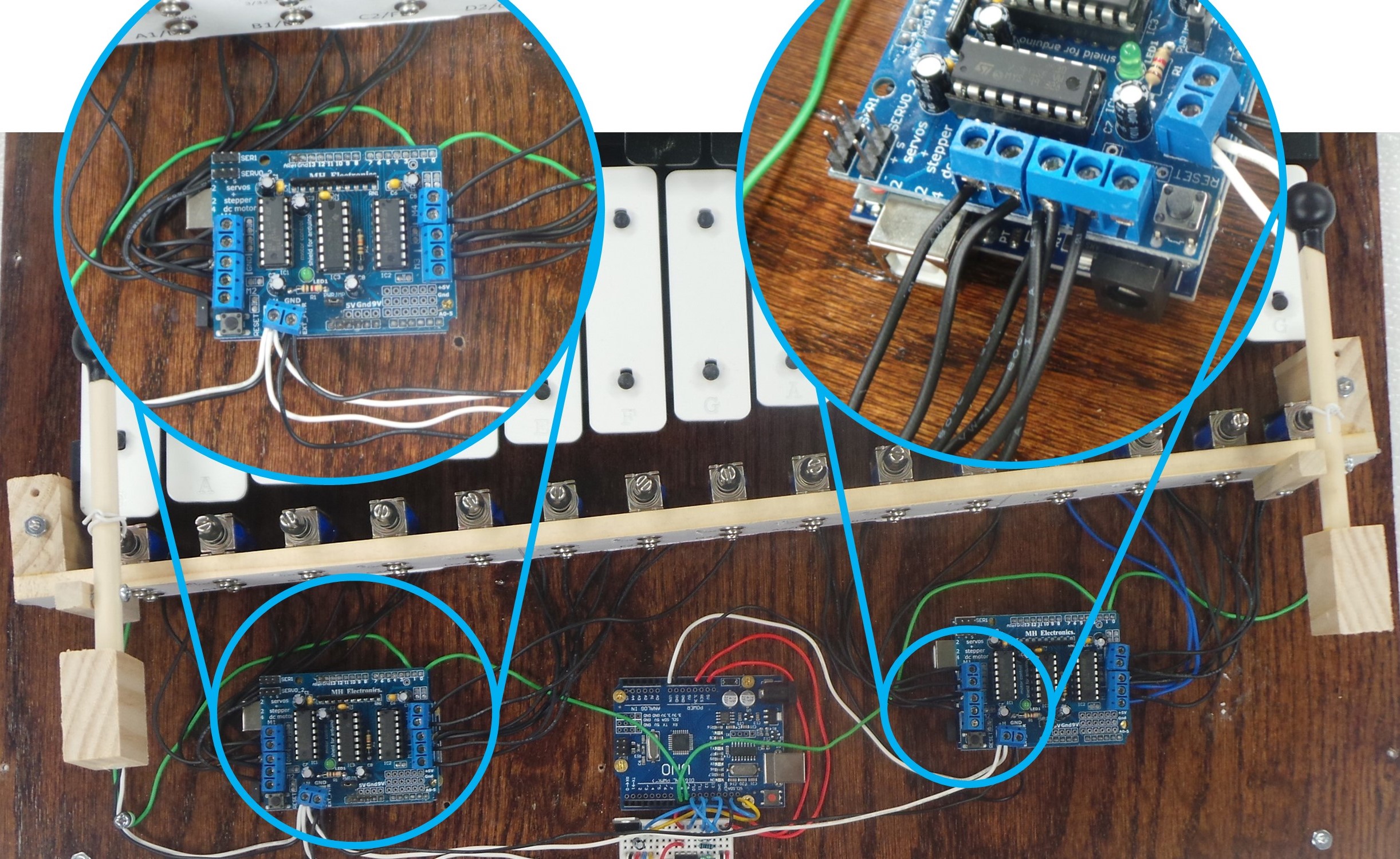
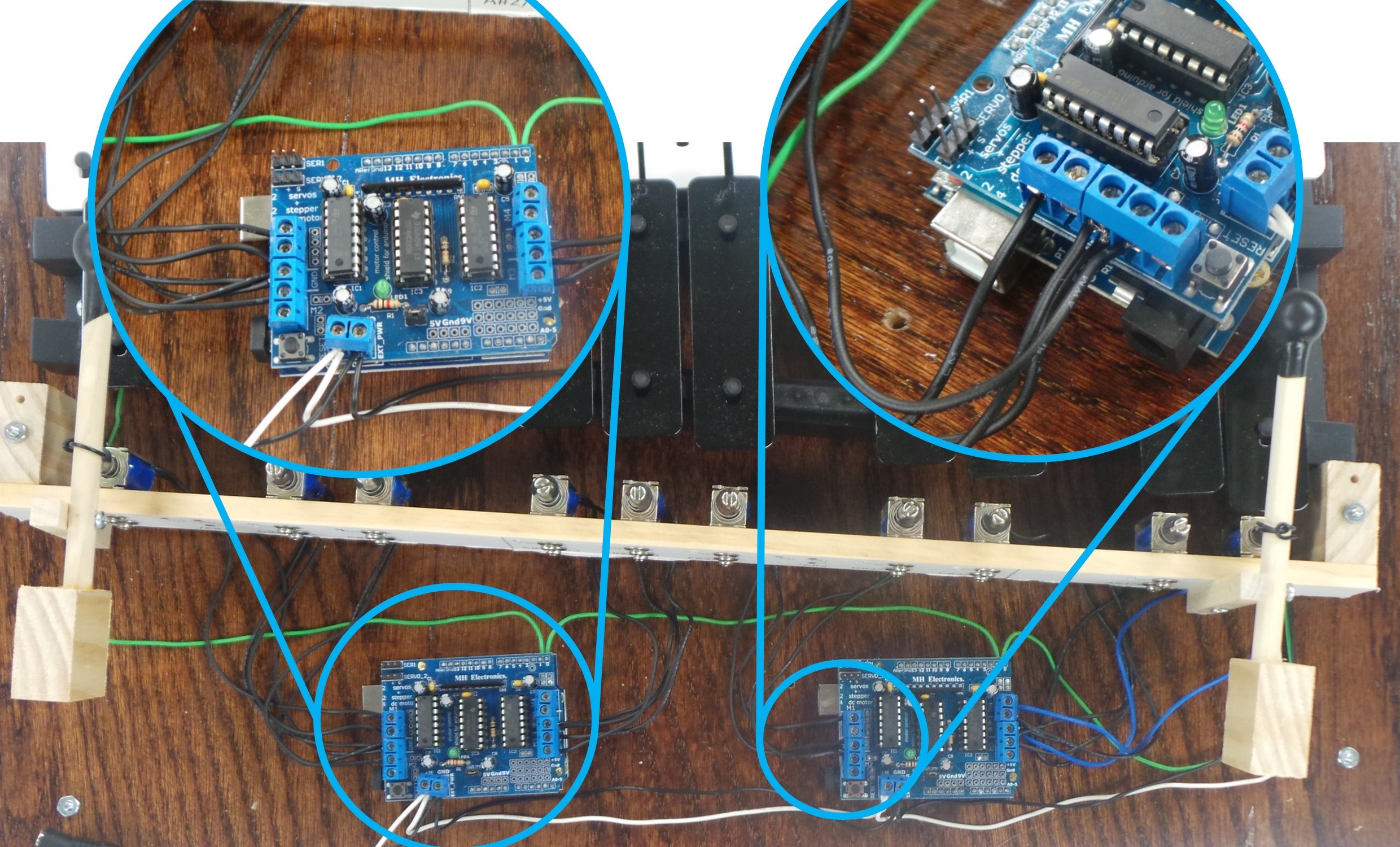
Prior to running this serial communication wire, you will need to drill 1/8″ diameter holes in the base, and screw in a #6-32 x 3/4″ machine screw at the places shown in the pictures. The 22-AWG hook-up wire can be twisted around the machine screw in order to secure it better.

Step 9: Using a Flush Diagonal Wire Cutter, remove pins 0 and 1 from all of the L293D Motor Driver Shields.

Step 10: Place the four Motor Driver Shields on top of the four Slave Arduinos. Make sure that the all of the pins on the Shields are inserted into the appropriate female header pins on the Arduino’s.
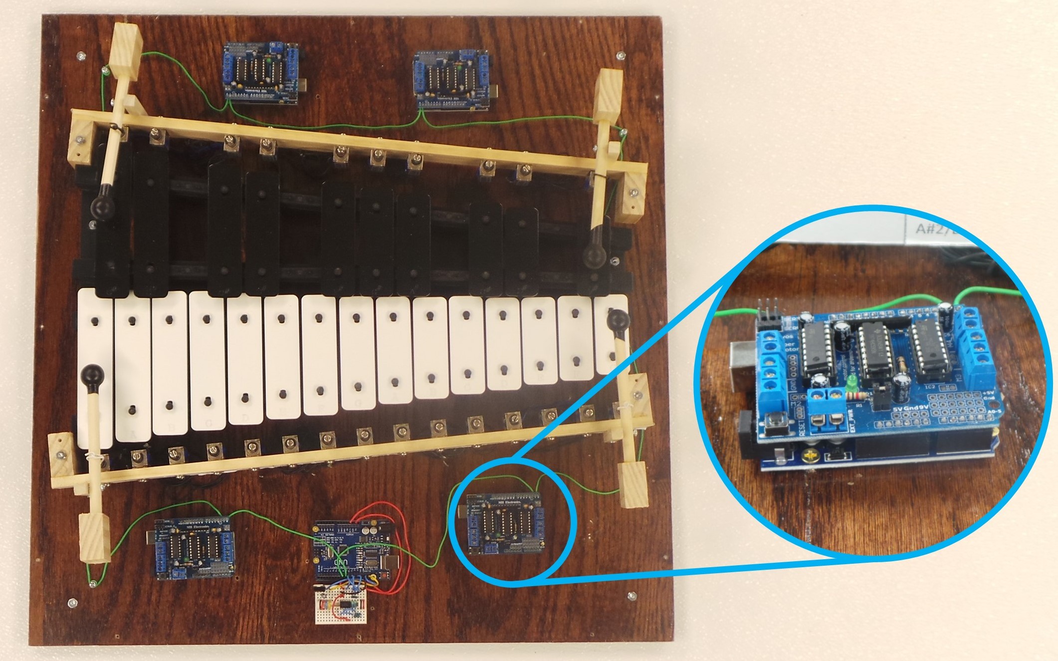
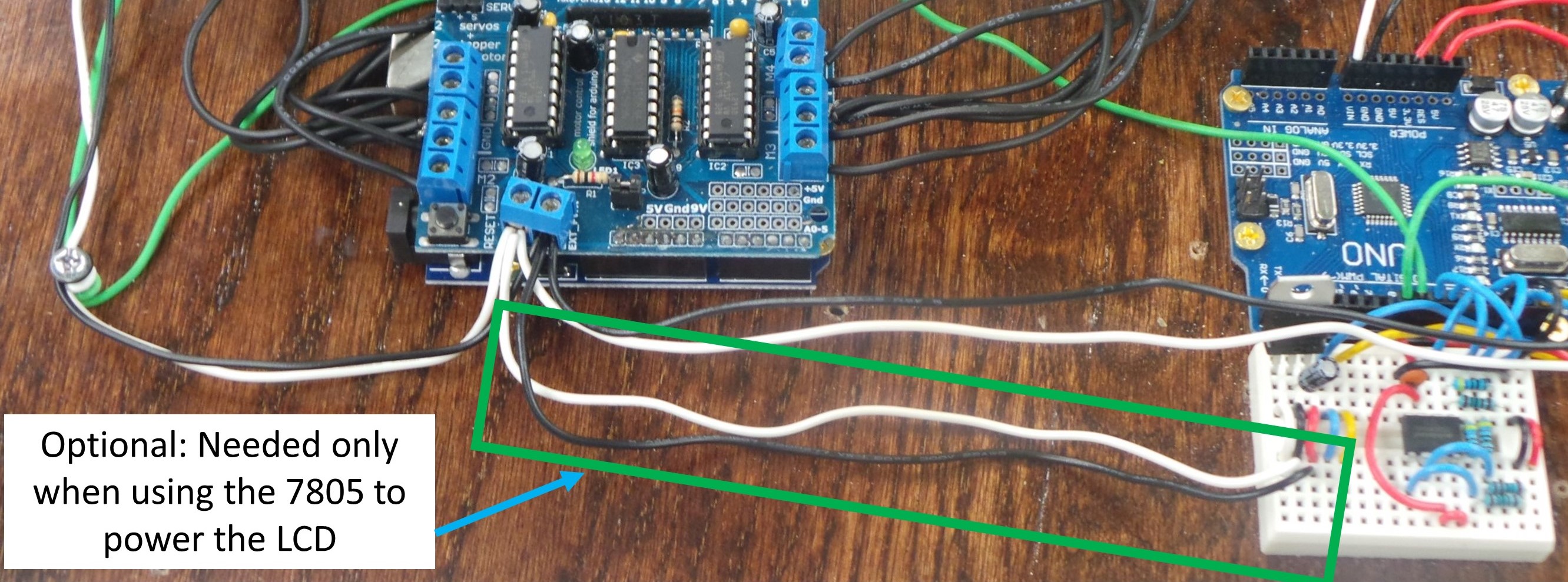
Step 11: Use 22 AWG hook-up wire to connect the +M and GND screw terminals of all of the Motor Driver Shields. This will provide the power for the solenoids. Also, run the power wire to the VIN and GND pins on the Arduino. From the last Shield, wire the 2.1mm DC Barrel Jack.
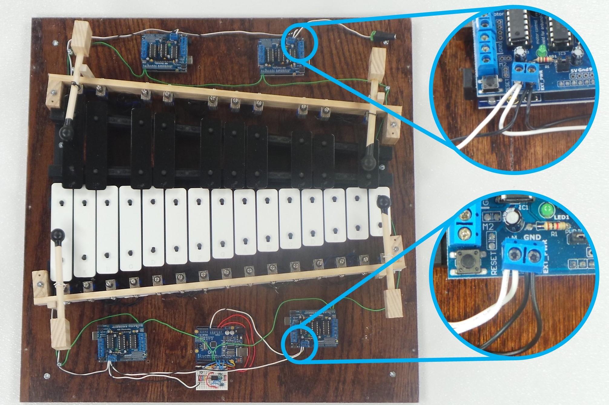
Here is a closer view of the back and front of the base with the power wires run.
Note that running the power wire from a Shield to the 7805 on the Breadboard is required only if using the 7805 to power the LCD.
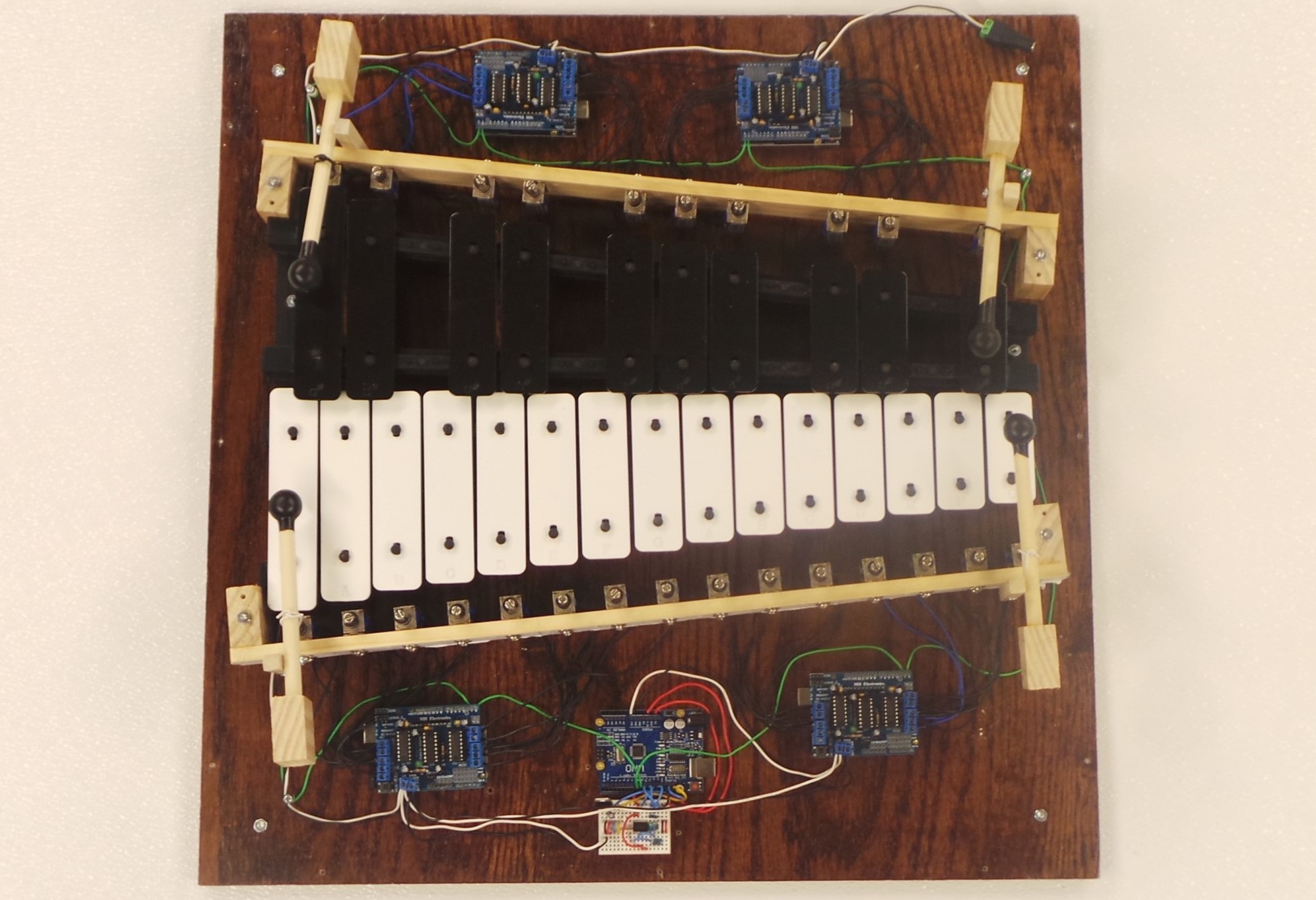
Step 12: Wire the solenoids into the Motor Driver Shields. Note that each shield can drive up to 8 solenoids. One wire from each solenoid needs to go to the GND terminal. There are only two of these on each shield, so up to four of these wires may need to be twisted together. The other wire from the Solenoid goes to the appropriate terminal that will drive a current (M1A, M1B, M2A, M2B, M3A, M3B, M4A, or M4B).
The entire xylophone assembly, when wired to the solenoids, looks like below.
Step 13: Connect the LCD and Rotary Encoder to the Master Ardunio. Pin connections are as shown below. Connect the USB Cable to the Arduino and Download the Main Program, as found on the Software page.

Here is where you check to make sure everything is wired up right.
If the LCD is wired correctly, it should show the Hardware Test menu. If the LCD is powered, but nothing is showing on the screen, turn the contrast pot on the back to see if anything shows up. If the first and third rows show solid boxes, the most likely cause is that the Arduino is using the wrong I2C address. In that case, refer to the comments within the “HardwareDefines.h” file in the main Arduino program to change the I2C address to something that works. If the LCD does not power on at all, make sure that the voltage at the VCC terminal is approximately 5V.
If the Rotary Encoder is wired correctly, you should be able to turn it to select an item from the menu. Make sure that you can move the cursor both up and down. You should be able to press down on the Rotary Encoder to select the current menu option. If any of this doesn’t work, make sure that the terminals on the Rotary Encoder are wired to the correct Arduino pins.
Step 14: To verify that the Winbond SPI Flash is wired correctly, use the “Memory Test” function. The Arduino will go through the sequence of identifying the SPI Flash chip, writing sample data to memory, and reading the data back. If everything is good, you will see the message “Memory Test Passed.”

If you do not get a “Memory Test Passed” the problem is almost always that the wiring is wrong. In a very rare case, you could get an error message if the chip is defective, but I have never seen this in all of my work with this component.
Step 15: Plug in the 12V 10A LED Power Supply and connect it to the DC Barrel Jack. If everything is good, you should see green lights on all of the Motor Driver Shields. You should also have power and on the LCD, and be able to turn the Rotary Encoder to navigate the menu, even if the USB is not connected.
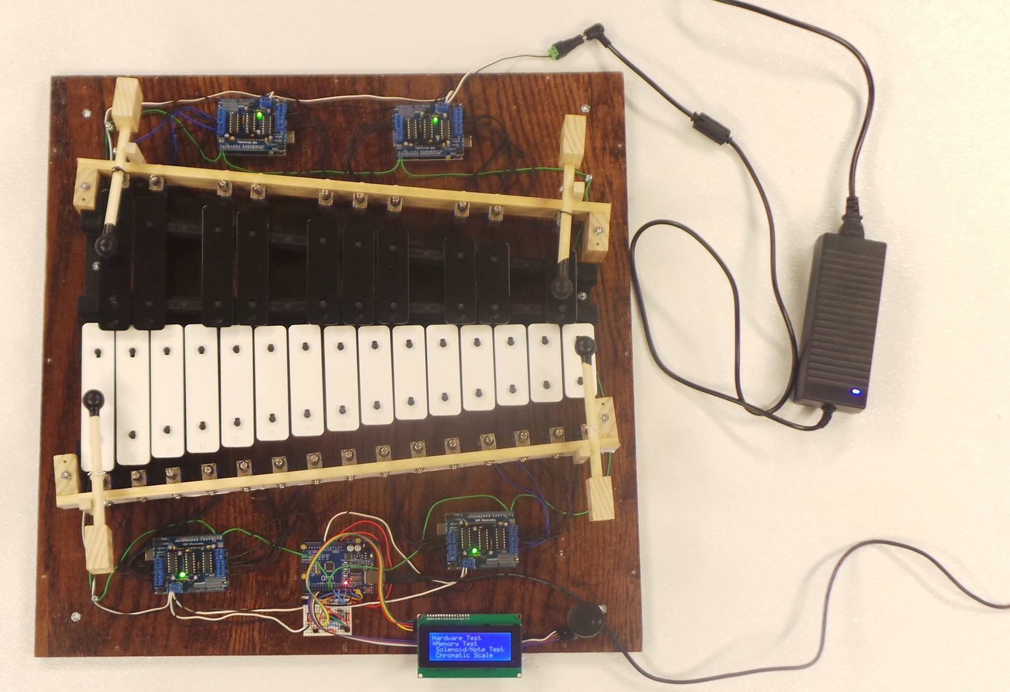
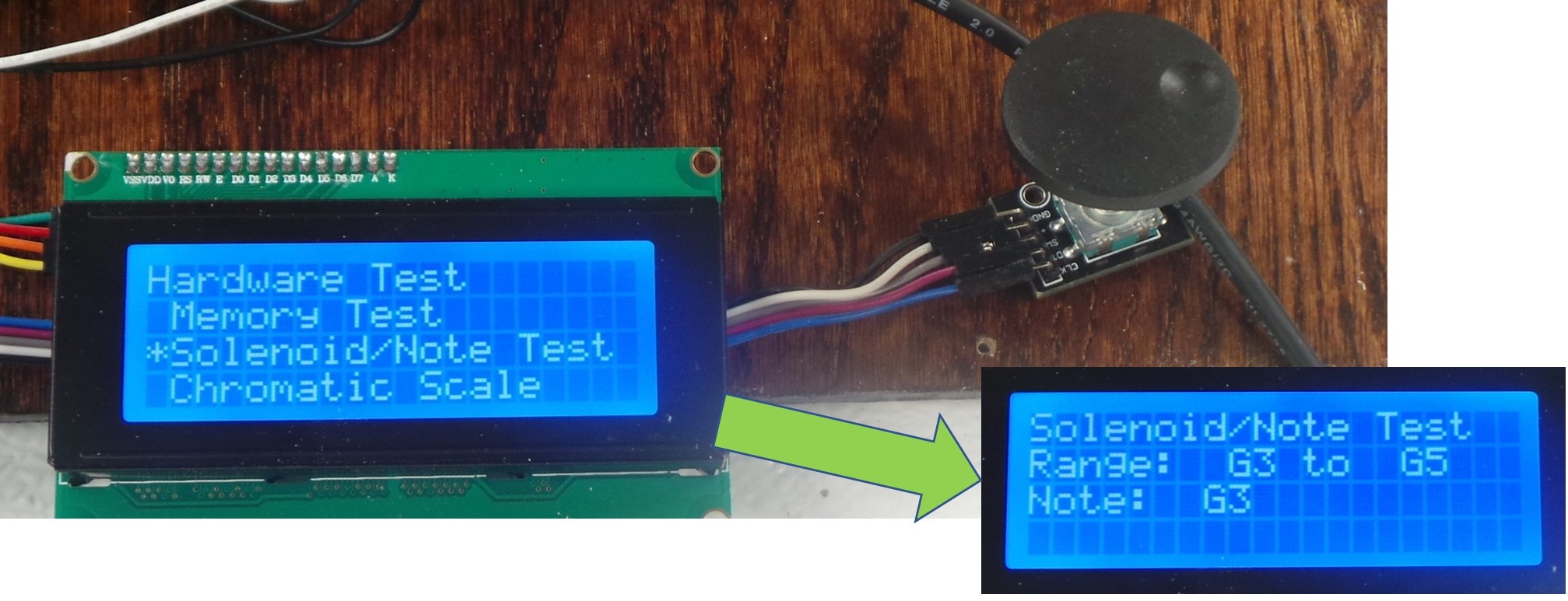
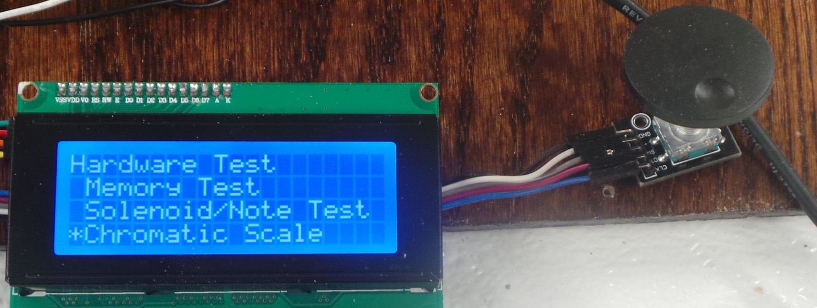
Step 16: Use the “Solenoid/Note Test” and “Chromatic Scale” options of the “Hardware Test” menu to make sure that all of the solenoids work correctly, and that they fire with the correct note. The “Solenoid/Note Test” option allows one to test a single solenoid. The Rotary Encoder is used to select which Solenoid/Note to test. The “Chromatic Scale” option will fire all solenoids to play all notes, in order from the lowest note to the highest note.
If any of this does not work as expected, the most likely cause is that either the solenoid is not wired into the motor driver shield correctly, or the Note Map definition within the HardwareDefines.h file does not match how the solenoids are wired into the shields.
Note on LCD Power: If you are powering the LCD directly from the Arduino, connect it as shown on the left picture below. (In that case, you don’t even need the voltage regulator as pictured.) Conversely, if powering the LCD from an external regulator, it is connected into the breadboard as shown on the right.

Next: Final Assembly
