
The final steps for putting the robotic xylophone together, are as follows:
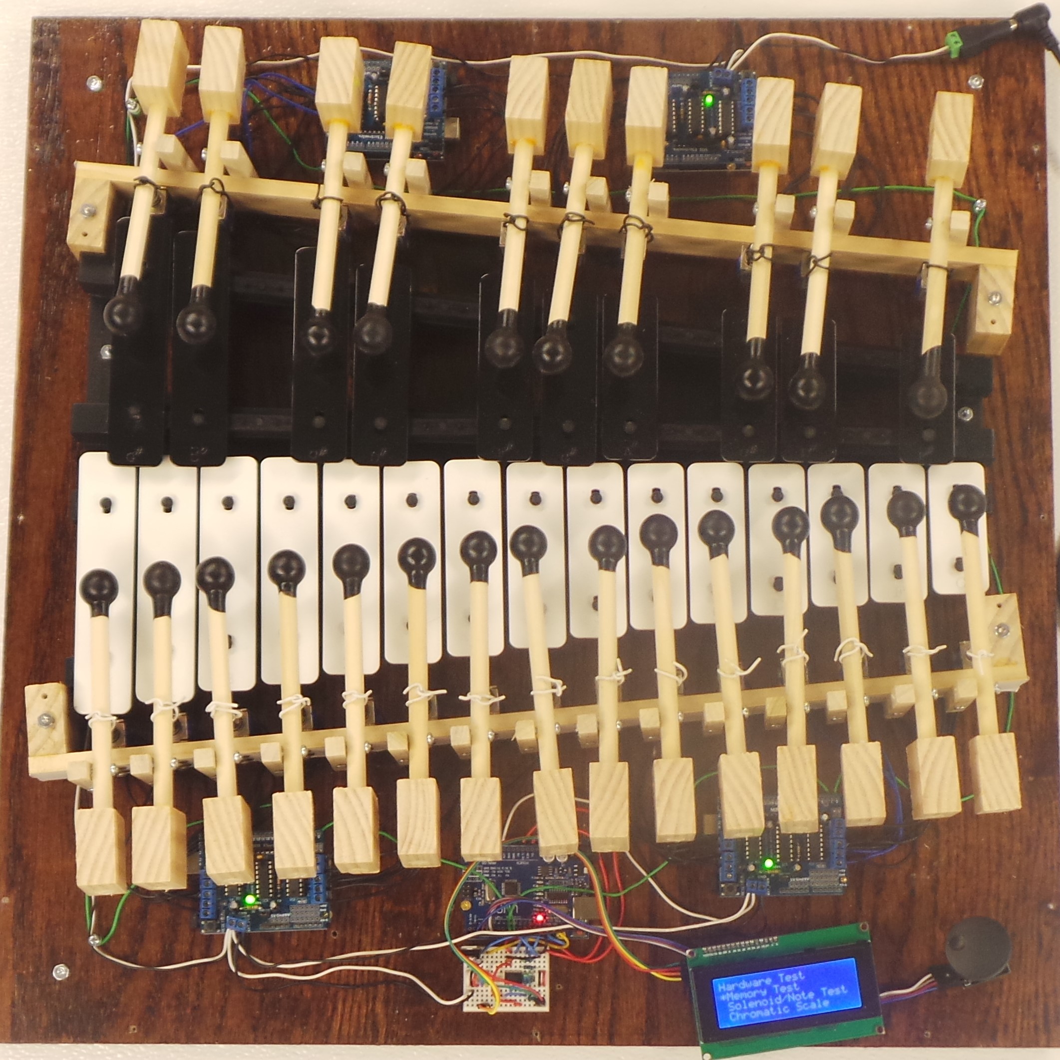
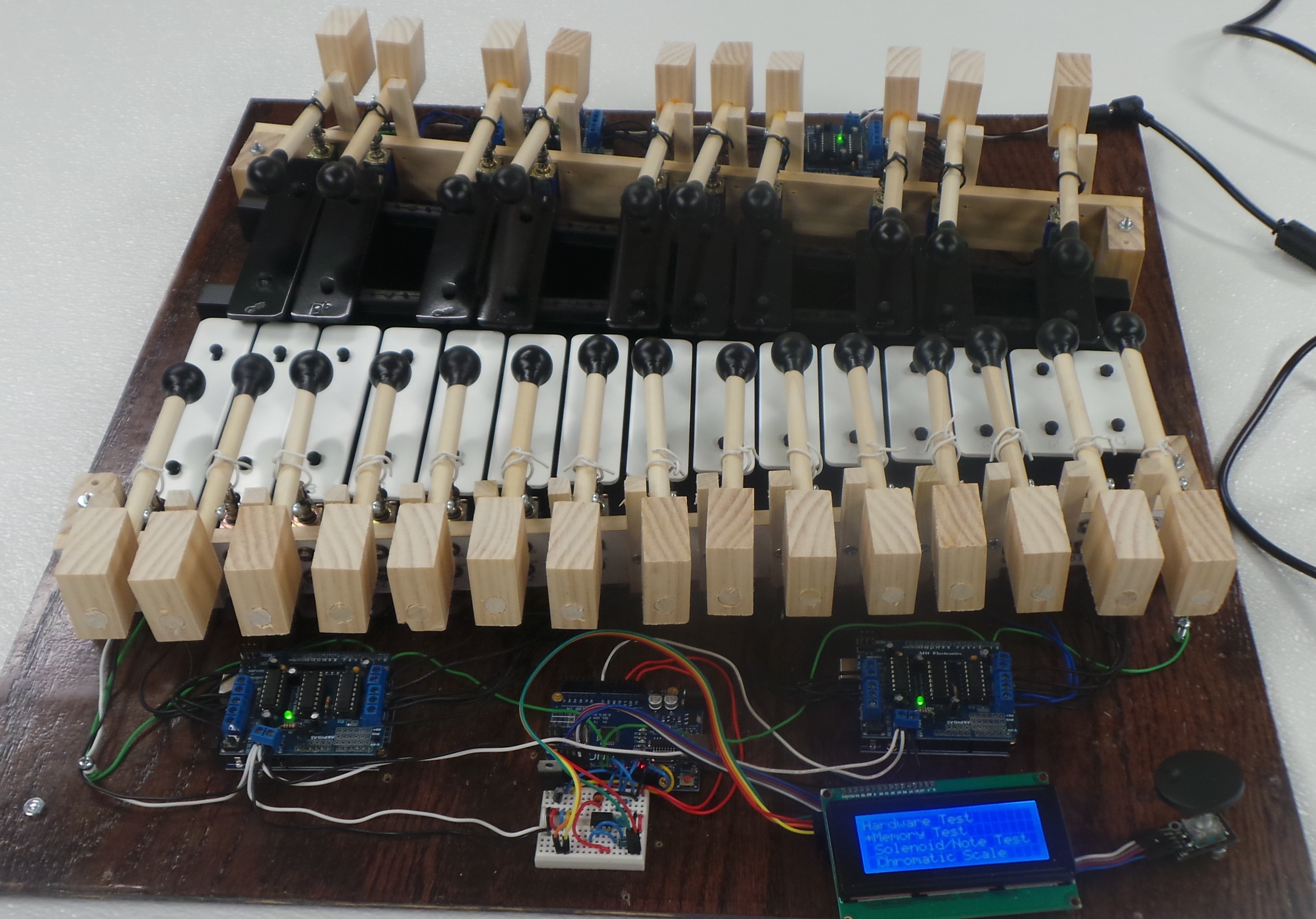
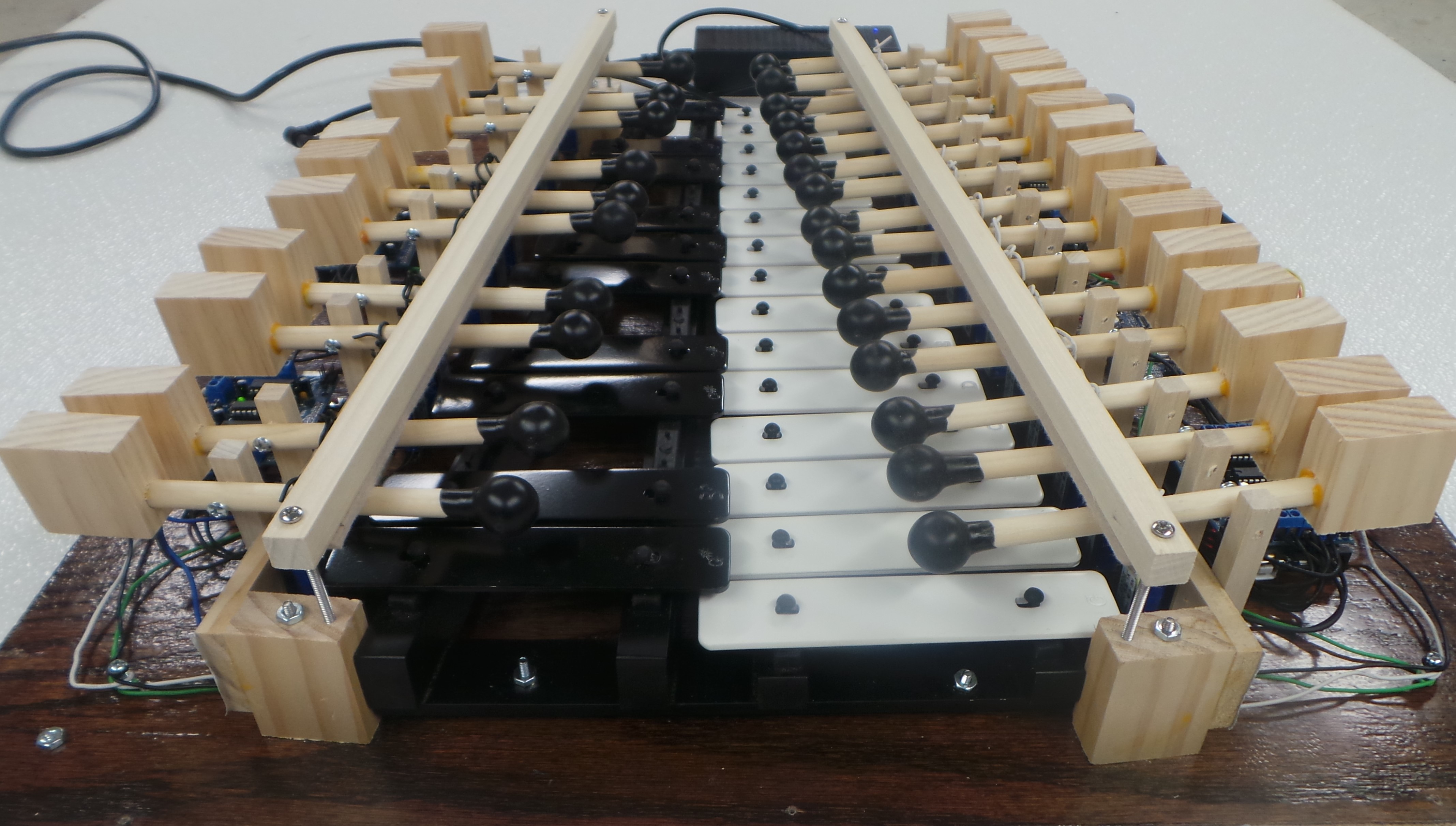
Step 1: Using the #6 x 3/4″ wood screws and 22 AWG hook-up wire, attach the remaining mallets to the Solenoid Boards. The xylophone will now look like below:
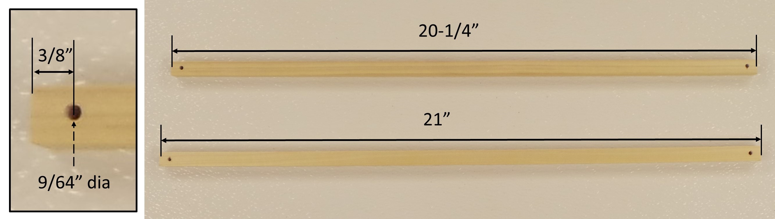
Step 2: Make the “Bumpers” for the mallets. Cut 1/2″ Square Dowels to lengths of 20-1/4″ and 21″, the same lengths as the Solenoid Boards. Drill 9/64″ diameter holes 3/8″ from each end.
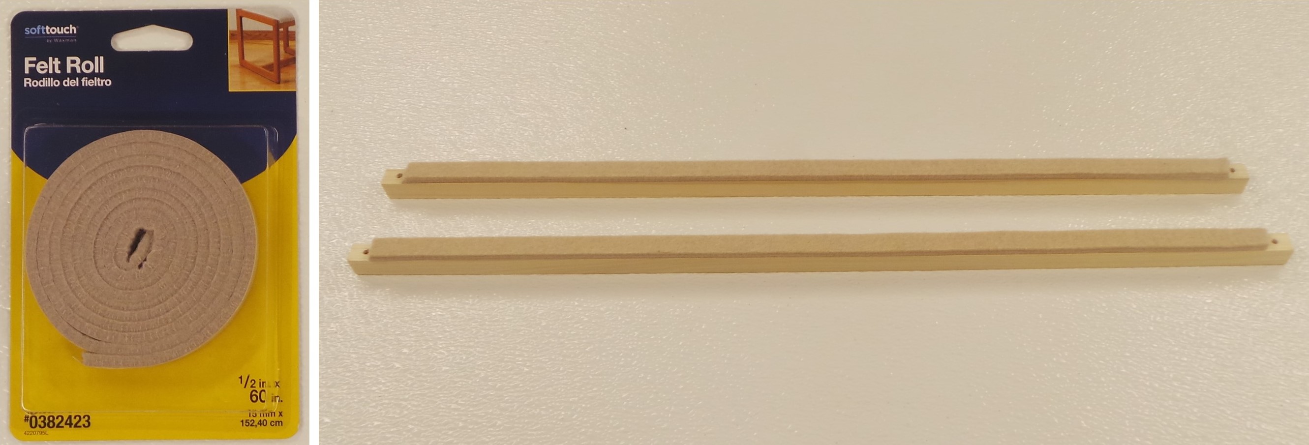
Cut lengths from the felt roll, long enough to cover all of the bumper, except for the ends with the holes.
Insert #6-32 x 2-1/2″ machine screws through the holes in the direction of the felt strip. Secure the machine screws using nylon insert lock nuts. The lock nuts should be tight enough so that the machine screws do not slide up and down the hole, but loose enough that the machine screws can still rotate in the hole.

Step 3: Screw the machine screws into the 1/8″ holes in the End Supports. You will need to screw one slide down a little, then the other side, and then back to the first side. Screw the Bumpers down enough so that the mallet heads are approximately 3/4″ above the surface of the xylophone bars.

Use the Solenoid/Note Test and the Chromatic Scale functions to make sure that all the notes on the xylophone play correctly, as shown in the video below.
When you are satisfied that everything plays right, you can proceed with putting the the enclosure together.
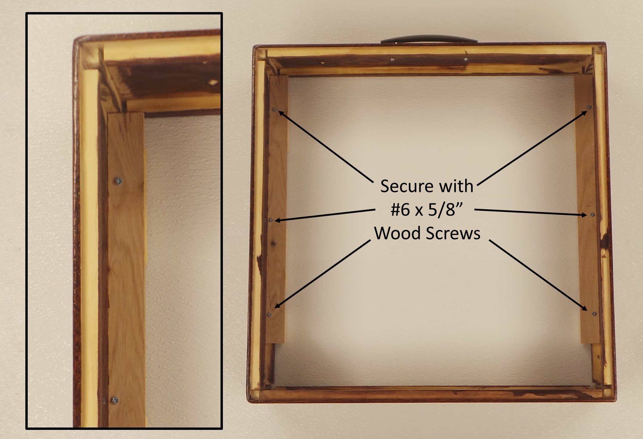
Step 4: Use six (6) #6 x 5/8″ Wood Screws to secure the Runners to the main enclosure, as shown below. Drill pilot holes so that the wood doesn’t split.
Step 5: Use the #8-32 x 3/4″ Machine Screws to attach the handle to the Back of the enclosure.

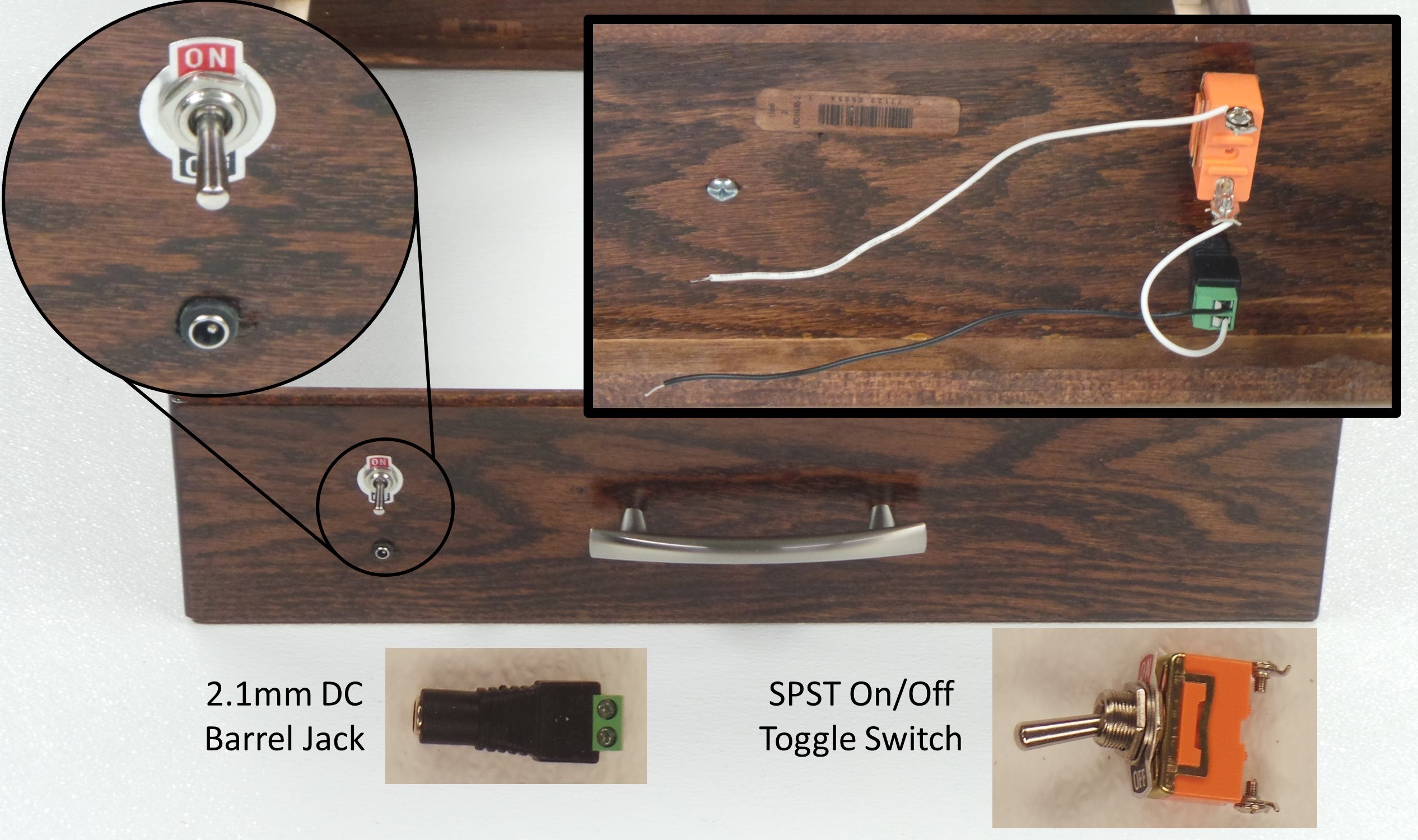
Step 6: Mount the On/Off Switch in the 1/2″ hole in the enclosure. Press the DC Barrel Jack into the 3/8″ hole. Wire the switch and barrel jack as shown below. Make sure that the “+” on the barrel jack goes to the White wire, and the “-” goes to the Black wire.
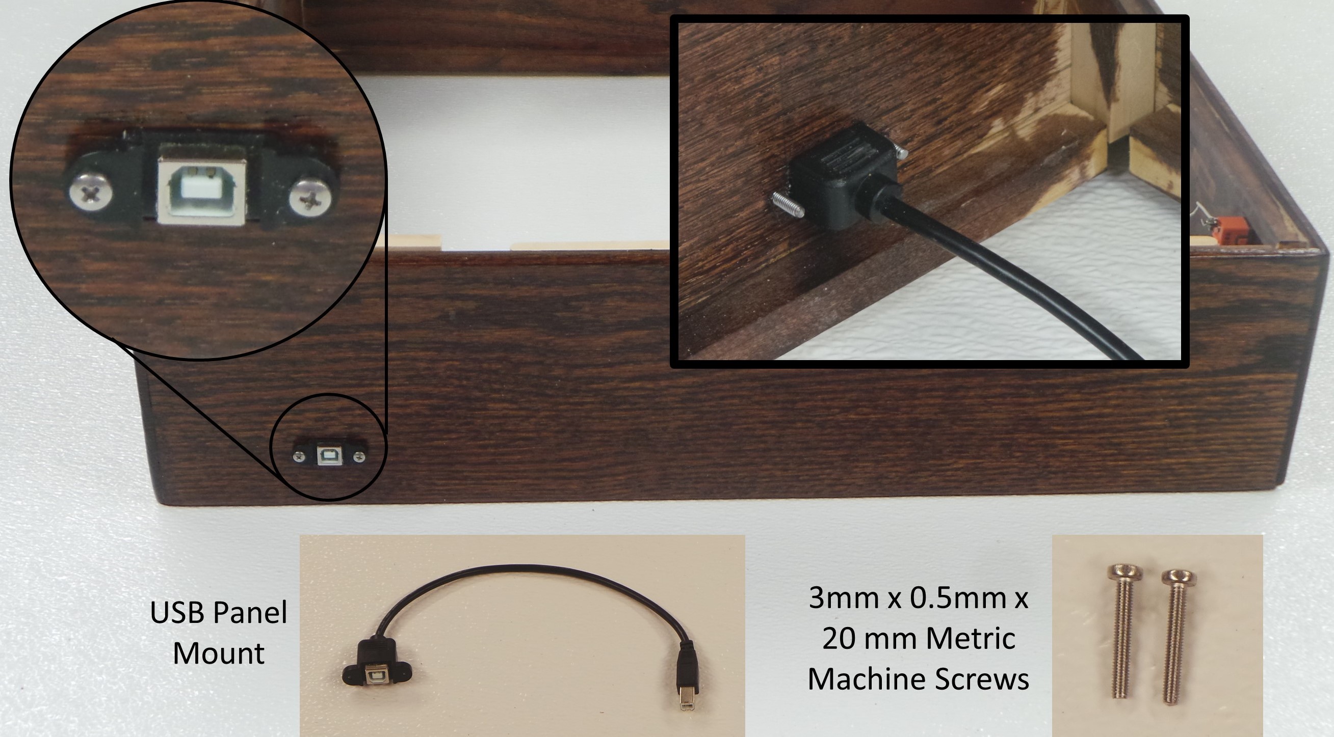
Step 7: Insert the USB Panel Mount into the rectangular hole on the side of the enclosure. Secure the Panel Mount using two (2) 3mm x 20mm Metric Machine Screws.
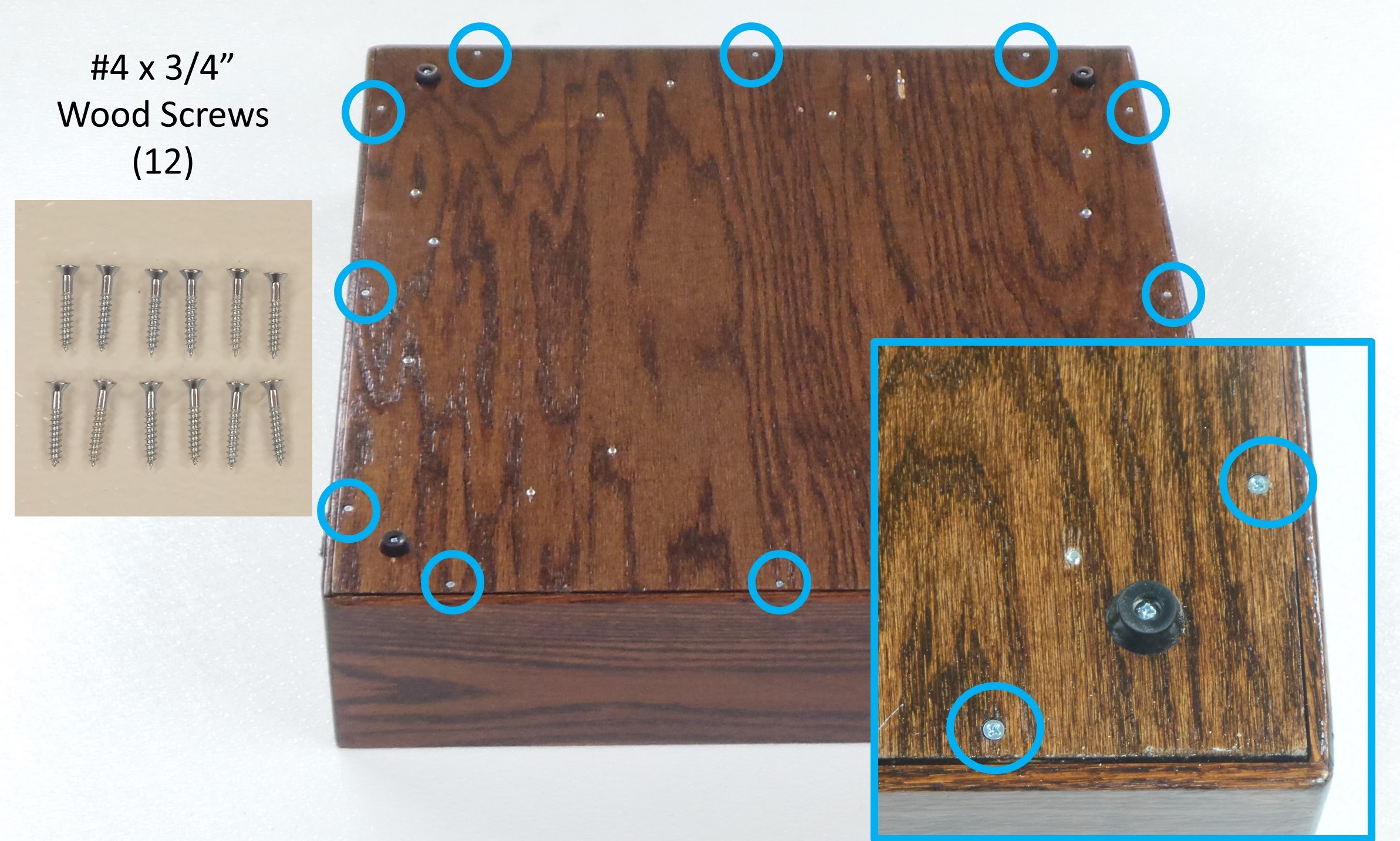
Step 8: Turn the enclosure sides upside down, and place the base with the xylophone and mallets upside down on top. Make sure that no wires get pinched between the base and the enclosure sides. Also make sure that the orientation of the base matches the sides (e.g. the Black notes of the xylophone facing the same side as the handle). Secure the base to the sides using twelve (12) #4 x 3/4″ wood screws.
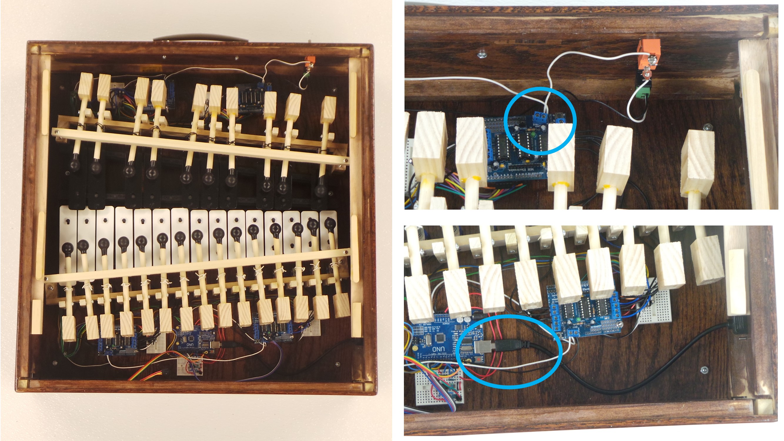
Step 9: Turn the enclosure right side up. Plug the USB Panel Mount into the Master Arduino Uno. Screw the Black and White power wires into the power terminals of the back-right Motor Driver Board.
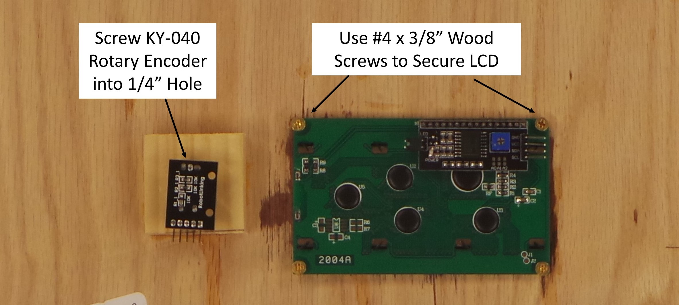
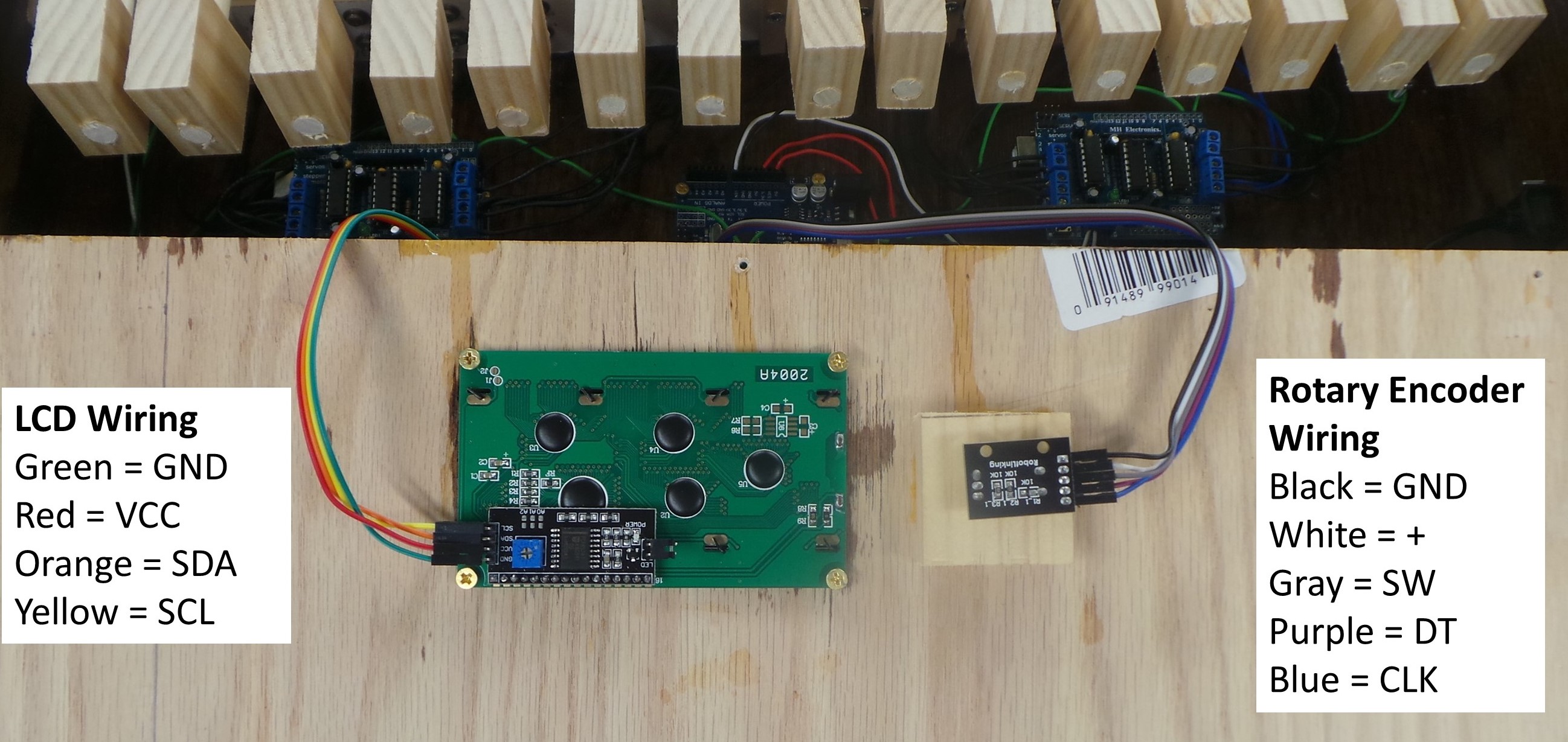
Step 10: Screw the Rotary Encoder into the hole in the Rotary Encoder Mount. Secure the LCD to the back using four (4) #4 x 3/8″ wood screws.
Step 11: Attach the jumper wires to the LCD and Rotary Encoder as shown below.
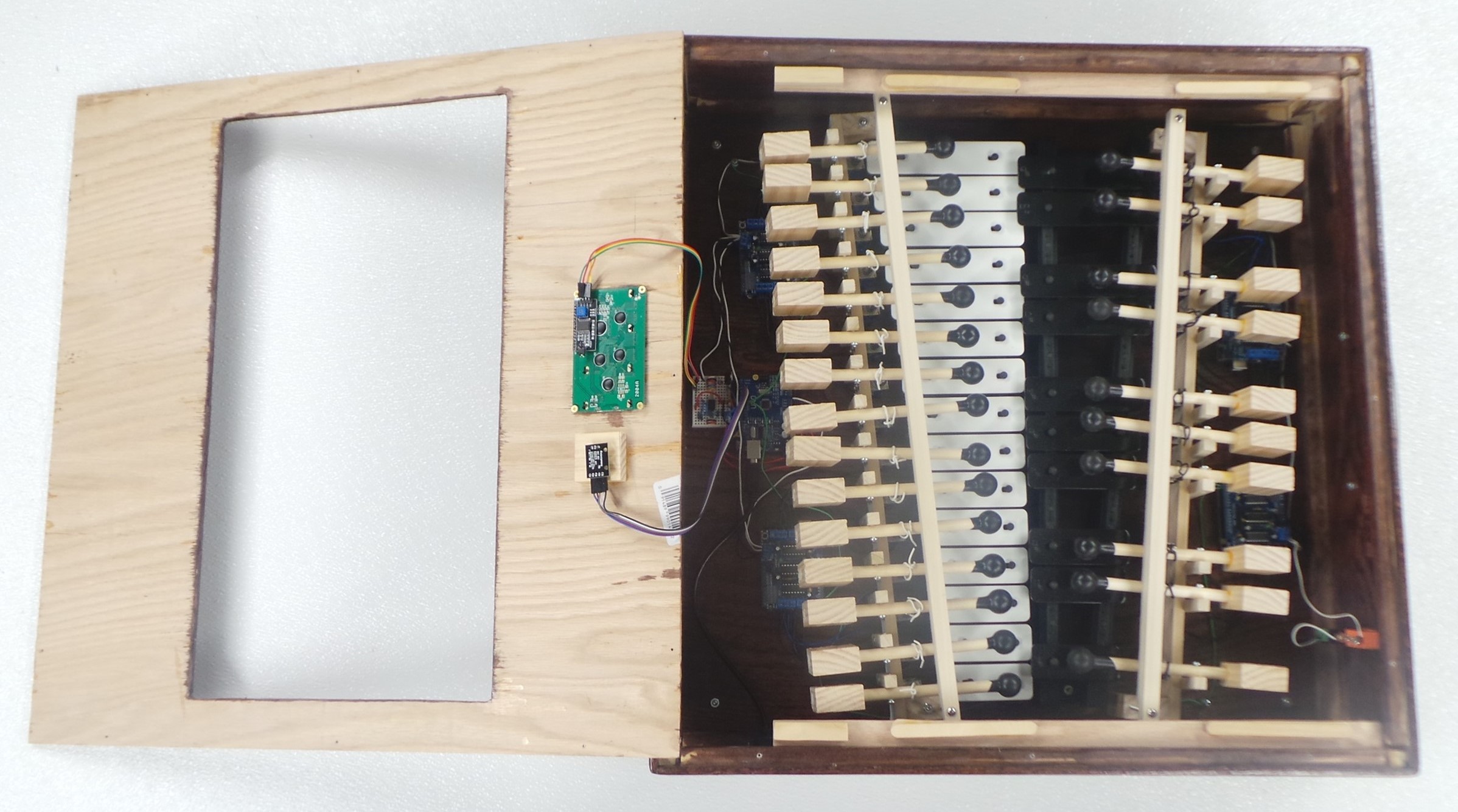
Step 12: Place the clear acrylic Window on top of the Runners. Place the Enclosure Top over it, making sure that the jumper wires to the LCD and Rotary Encoder stay connected. Secure the Enclosure Top using twelve (12) #4 x 3/4″ Wood Screws.
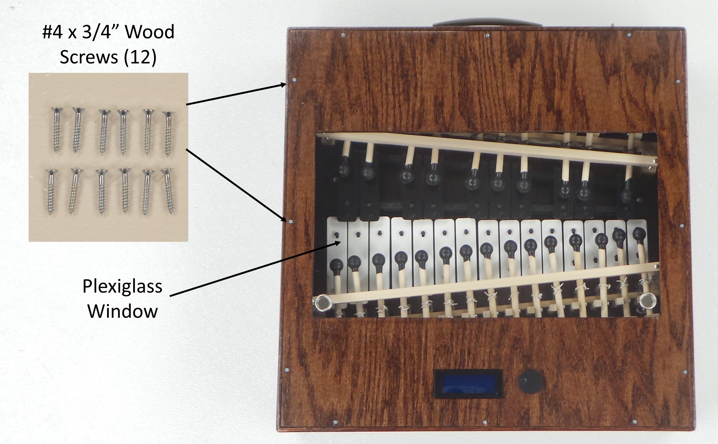
Tighten the screws enough so that the Top is secure, and they are not sticking up too much above the surface of the plywood. But don’t tighten them so much that the Window can’t slide. The Window should be loose enough so that it can slide along the runners using 1 finger on each pull, but tight enough so that the Window stays in place after sliding.

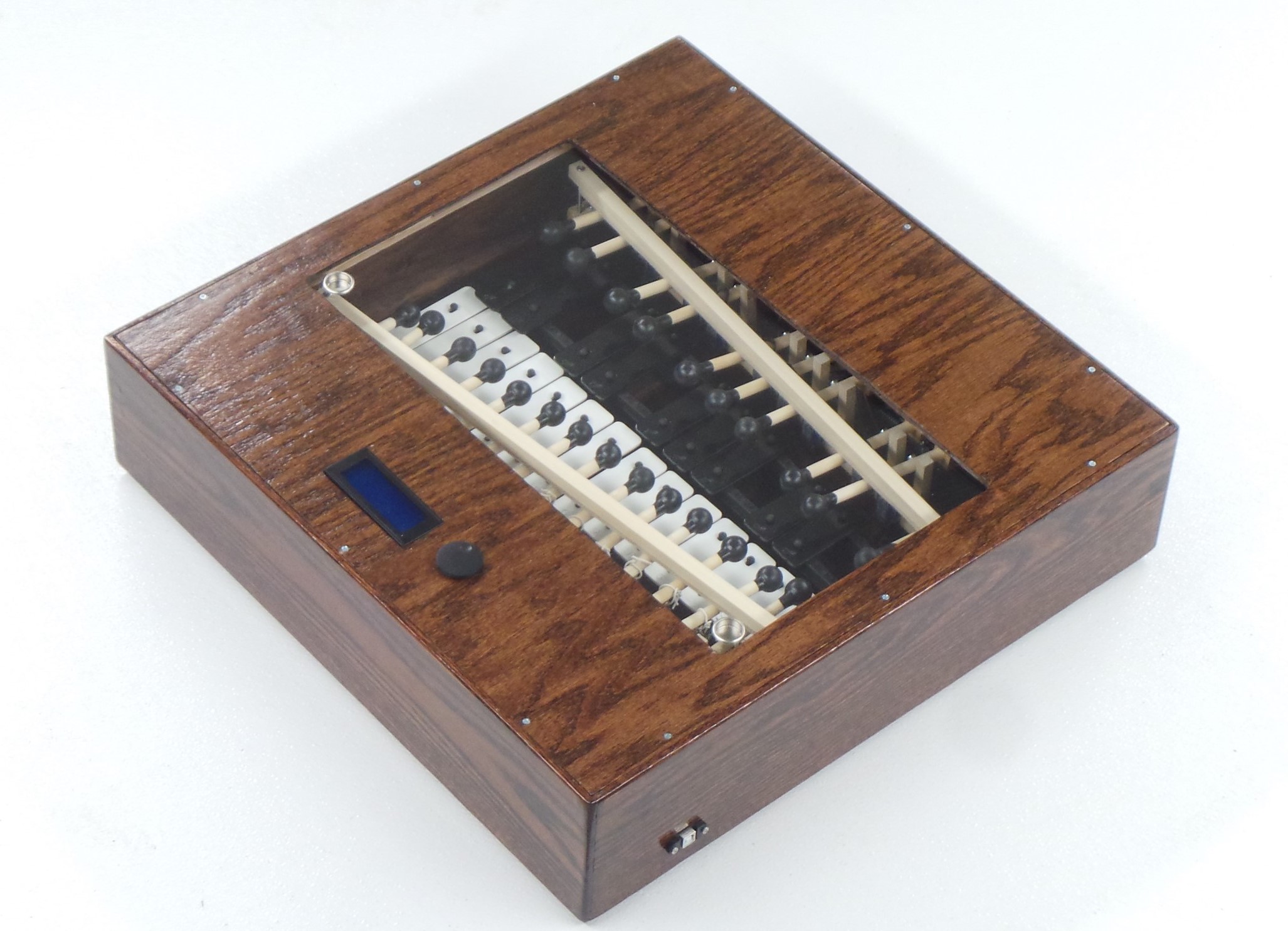
The completed robotic xylophone will look like the picture below.
When the Final Assembly is complete, power-up the xylophone, and make sure all the components (e.g. LCD and Rotary Encoder) still work. Use the Chromatic Scale test to make sure that all the mallets still work correctly, and the sound is still good.
Next: Software
